Information injection-pump assembly
ZEXEL
101401-9770
1014019770
Rating:
Cross reference number
ZEXEL
101401-9770
1014019770
Zexel num
Bosch num
Firm num
Name
101401-9770
INJECTION-PUMP ASSEMBLY
Calibration Data:
Adjustment conditions
Test oil
1404 Test oil ISO4113 or {SAEJ967d}
1404 Test oil ISO4113 or {SAEJ967d}
Test oil temperature
degC
40
40
45
Nozzle and nozzle holder
105780-8140
Bosch type code
EF8511/9A
Nozzle
105780-0000
Bosch type code
DN12SD12T
Nozzle holder
105780-2080
Bosch type code
EF8511/9
Opening pressure
MPa
17.2
Opening pressure
kgf/cm2
175
Injection pipe
Outer diameter - inner diameter - length (mm) mm 6-2-600
Outer diameter - inner diameter - length (mm) mm 6-2-600
Overflow valve
134424-4120
Overflow valve opening pressure
kPa
255
221
289
Overflow valve opening pressure
kgf/cm2
2.6
2.25
2.95
Tester oil delivery pressure
kPa
157
157
157
Tester oil delivery pressure
kgf/cm2
1.6
1.6
1.6
Direction of rotation (viewed from drive side)
Right R
Right R
Injection timing adjustment
Direction of rotation (viewed from drive side)
Right R
Right R
Injection order
1-3-4-2
Pre-stroke
mm
3.2
3.15
3.25
Rack position
Point A R=A
Point A R=A
Beginning of injection position
Drive side NO.1
Drive side NO.1
Difference between angles 1
Cal 1-3 deg. 90 89.5 90.5
Cal 1-3 deg. 90 89.5 90.5
Difference between angles 2
Cal 1-4 deg. 180 179.5 180.5
Cal 1-4 deg. 180 179.5 180.5
Difference between angles 3
Cyl.1-2 deg. 270 269.5 270.5
Cyl.1-2 deg. 270 269.5 270.5
Injection quantity adjustment
Adjusting point
-
Rack position
14.6
Pump speed
r/min
1550
1550
1550
Average injection quantity
mm3/st.
108.5
106.9
110.1
Max. variation between cylinders
%
0
-3.5
3.5
Basic
*
Fixing the rack
*
Standard for adjustment of the maximum variation between cylinders
*
Injection quantity adjustment_02
Adjusting point
H
Rack position
9.7+-0.5
Pump speed
r/min
325
325
325
Average injection quantity
mm3/st.
13
11.2
14.8
Max. variation between cylinders
%
0
-10
10
Fixing the rack
*
Standard for adjustment of the maximum variation between cylinders
*
Injection quantity adjustment_03
Adjusting point
A
Rack position
R1(14.6)
Pump speed
r/min
1550
1550
1550
Average injection quantity
mm3/st.
108.5
107.5
109.5
Basic
*
Fixing the lever
*
Boost pressure
kPa
70.6
70.6
Boost pressure
mmHg
530
530
Injection quantity adjustment_04
Adjusting point
B
Rack position
R1-1.05
Pump speed
r/min
900
900
900
Average injection quantity
mm3/st.
88
84
92
Fixing the lever
*
Boost pressure
kPa
70.6
70.6
Boost pressure
mmHg
530
530
Injection quantity adjustment_05
Adjusting point
C
Rack position
R2-0.95
Pump speed
r/min
500
500
500
Average injection quantity
mm3/st.
58
54
62
Fixing the lever
*
Boost pressure
kPa
0
0
0
Boost pressure
mmHg
0
0
0
Boost compensator adjustment
Pump speed
r/min
500
500
500
Rack position
R2-0.95
Boost pressure
kPa
10.7
9.4
12
Boost pressure
mmHg
80
70
90
Boost compensator adjustment_02
Pump speed
r/min
500
500
500
Rack position
R2(R1-1.
35)
Boost pressure
kPa
57.3
57.3
57.3
Boost pressure
mmHg
430
430
430
Timer adjustment
Pump speed
r/min
1000--
Advance angle
deg.
0
0
0
Remarks
Start
Start
Timer adjustment_02
Pump speed
r/min
950
Advance angle
deg.
0.5
Timer adjustment_03
Pump speed
r/min
1550
Advance angle
deg.
5.1
4.6
5.6
Timer adjustment_04
Pump speed
r/min
-
Advance angle
deg.
7
6.5
7.5
Remarks
Measure the actual speed, stop
Measure the actual speed, stop
Test data Ex:
Governor adjustment
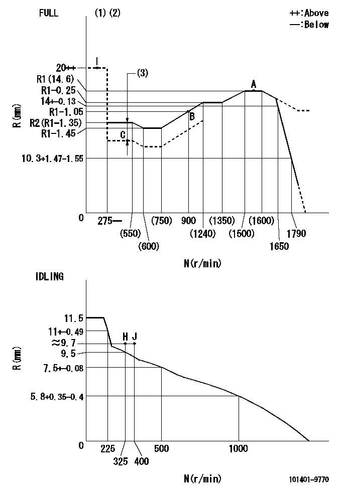
N:Pump speed
R:Rack position (mm)
(1)Torque cam stamping: T1
(2)Tolerance for racks not indicated: +-0.05mm.
(3)Boost compensator stroke: BCL
----------
T1=L33 BCL=0.95+-0.1mm
----------
----------
T1=L33 BCL=0.95+-0.1mm
----------
Speed control lever angle
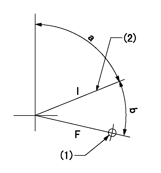
F:Full speed
I:Idle
(1)Use the hole at R = aa
(2)Stopper bolt set position 'H'
----------
aa=32mm
----------
a=71deg+-5deg b=(38deg)+-3deg
----------
aa=32mm
----------
a=71deg+-5deg b=(38deg)+-3deg
Stop lever angle

N:Pump normal
S:Stop the pump.
(1)Use the pin at R = aa
----------
aa=12mm
----------
a=29deg+-5deg b=10deg+-5deg
----------
aa=12mm
----------
a=29deg+-5deg b=10deg+-5deg
0000001501 LEVER
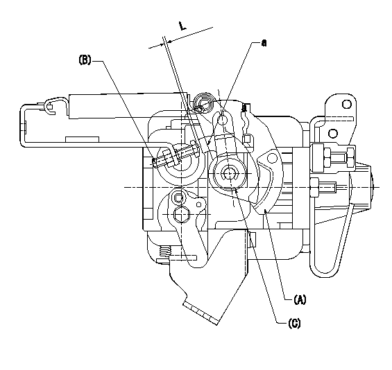
(A) Speed lever (lower)
(B) Stopper bolt
(C) Special lever (upper)
a:Point A (inside lever)
1. Special lever adjustment
(1)With the speed lever at the idle position, set the accelerator lever stopper bolt so that the accelerator lever contacts the speed lever at point a.
(2)Back off the stopper bolt L and set.
----------
L=1+0.5mm
----------
----------
L=1+0.5mm
----------
0000001601 POTENTIO METER
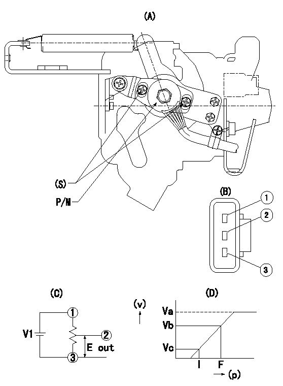
(A) : Governor plan view
(B): Potentiometer harness terminal
(C): Potentiometer connection diagram
(D) : Output voltage standard value
(S): Voltage
P/M: potentiometer
(v): output voltage (V)
(p): direction of potentiometer rotation
1. Adjustment procedures
(1)Apply DCV1 to potentiometer harness terminal (B) to obtain the specified output voltage.
(2)Fix the speed lever at the full side.
(3)Loosen the bolt (S), and move the potentiometer from left and right.
(4)Adjust so that the output voltage at full is within the standard values.
(5)Fix bolt (S).
(6)Repeatedly move the speed lever from the full side to the idle side.
(7)Check that it is within the standard values at full and idle.
----------
V1=5+-0.02V
----------
V1=5+-0.02V Va=(5)V Vb=(3.75)+-0.2V Vc=0.58+-0.3V
----------
V1=5+-0.02V
----------
V1=5+-0.02V Va=(5)V Vb=(3.75)+-0.2V Vc=0.58+-0.3V
Timing setting

(1)Pump vertical direction
(2)Position of gear's standard threaded hole at No 1 cylinder's beginning of injection
(3)B.T.D.C.: aa
(4)-
----------
aa=5deg
----------
a=(50deg)
----------
aa=5deg
----------
a=(50deg)
Information:
Table 4 is an example for using the equation that is in Table 3.
Table 4
Example of the Equation for the Addition of Cat SCA To Water For Maintenance
Total Volume of the Cooling System (V) Multiplication
Factor Amount of Cat SCA that is Required (X)
946 L
(250 US gal) × 0.023 22 L
(6 US gal) Note: Specific engine applications may require maintenance practices to be periodically evaluated to maintain the engine cooling system properly.Cleaning the System of Heavy-Duty Coolant/Antifreeze
Before Cat SCA can be effective, the cooling system must be free from rust, scale, and other deposits. Preventive cleaning helps avoid downtime caused by expensive out-of-service cleaning required for extremelydirty and neglected cooling systems.Cat Cooling System Cleaners
Dissolves or depresses mineral scales, corrosion products, light oil contaminations, and sludges
Cleans the cooling system after used coolant is drained or before the cooling system is filled with new coolant
Cleans the cooling system whenever the coolant is contaminated or whenever the coolant is foaming
The “Standard” version of the Cat Cooling System Cleaners clean the cooling system while still in service.
Reduces downtime and cleaning costs
Helps avoid costly repairs from pitting and other internal problems caused by improper cooling system maintenance
Can be used with glycol-based antifreeze
For the recommended service interval, refer to the Operation and Maintenance Manual, "Maintenance Interval Schedule" for your engine.Cat Standard Cooling System Cleaners are designed to clean the cooling system of harmful scale and corrosion without removing the engine from service. The cleaners, both “Standard” and “Quick Flush” can be used in all Cat engine cooling systems. Consult your Cat dealer for part numbers.Note: These cleaners must not be used in systems that have been neglected or that have heavy scale buildup. These systems require a stronger commercial solvent that is available from local distributors.Prior to performing a cleaning of the cooling system, take a 1-liter (1-quart) sample of coolant from the engine while in operation into a clear container. Take the sample shortly after start-up while the coolant is not yet hot. The coolant should be adequately mixed by the water pump. Allow the sample
Have questions with 101401-9770?
Group cross 101401-9770 ZEXEL
Mazda
Nissan-Diesel
Nissan-Diesel
101401-9770
INJECTION-PUMP ASSEMBLY