Information injection-pump assembly
ZEXEL
101401-9610
1014019610

Rating:
Cross reference number
ZEXEL
101401-9610
1014019610
Zexel num
Bosch num
Firm num
Name
Calibration Data:
Adjustment conditions
Test oil
1404 Test oil ISO4113 or {SAEJ967d}
1404 Test oil ISO4113 or {SAEJ967d}
Test oil temperature
degC
40
40
45
Nozzle and nozzle holder
105780-8140
Bosch type code
EF8511/9A
Nozzle
105780-0000
Bosch type code
DN12SD12T
Nozzle holder
105780-2080
Bosch type code
EF8511/9
Opening pressure
MPa
17.2
Opening pressure
kgf/cm2
175
Injection pipe
Outer diameter - inner diameter - length (mm) mm 6-2-600
Outer diameter - inner diameter - length (mm) mm 6-2-600
Overflow valve
131424-5620
Overflow valve opening pressure
kPa
157
123
191
Overflow valve opening pressure
kgf/cm2
1.6
1.25
1.95
Tester oil delivery pressure
kPa
157
157
157
Tester oil delivery pressure
kgf/cm2
1.6
1.6
1.6
Direction of rotation (viewed from drive side)
Right R
Right R
Injection timing adjustment
Direction of rotation (viewed from drive side)
Right R
Right R
Injection order
1-3-4-2
Pre-stroke
mm
3.9
3.85
3.95
Beginning of injection position
Drive side NO.1
Drive side NO.1
Difference between angles 1
Cal 1-3 deg. 90 89.5 90.5
Cal 1-3 deg. 90 89.5 90.5
Difference between angles 2
Cal 1-4 deg. 180 179.5 180.5
Cal 1-4 deg. 180 179.5 180.5
Difference between angles 3
Cyl.1-2 deg. 270 269.5 270.5
Cyl.1-2 deg. 270 269.5 270.5
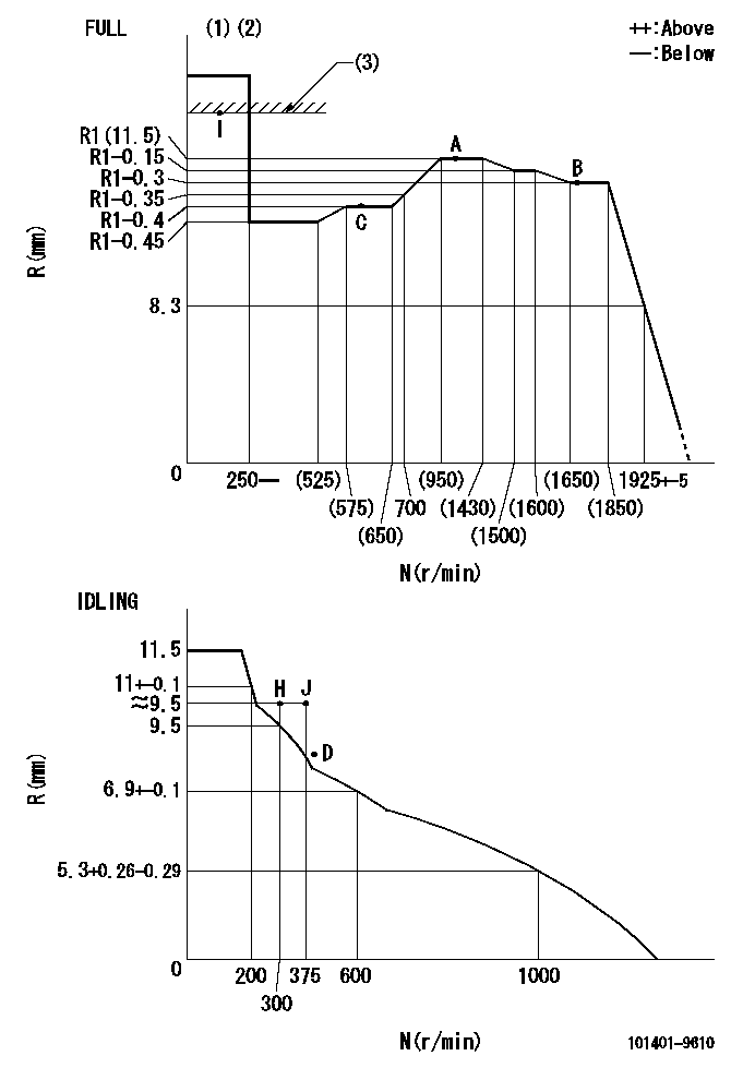
Injection quantity adjustment
Adjusting point
-
Rack position
11.5+-0.
5
Pump speed
r/min
1000
1000
1000
Each cylinder's injection qty
mm3/st.
60
58.5
61.5
Basic
*
Fixing the rack
*
Standard for adjustment of the maximum variation between cylinders
*
Injection quantity adjustment_02
Adjusting point
H
Rack position
9.5+-0.5
Pump speed
r/min
300
300
300
Each cylinder's injection qty
mm3/st.
15
12.7
17.3
Fixing the rack
*
Standard for adjustment of the maximum variation between cylinders
*
Injection quantity adjustment_03
Adjusting point
A
Rack position
R1(11.5)
Pump speed
r/min
1000
1000
1000
Average injection quantity
mm3/st.
60
59
61
Basic
*
Fixing the lever
*
Injection quantity adjustment_04
Adjusting point
B
Rack position
R1-0.3
Pump speed
r/min
1700
1700
1700
Average injection quantity
mm3/st.
56
52
60
Fixing the lever
*
Injection quantity adjustment_05
Adjusting point
C
Rack position
R1-0.4
Pump speed
r/min
600
600
600
Average injection quantity
mm3/st.
39.6
35.6
43.6
Fixing the lever
*
Injection quantity adjustment_06
Adjusting point
I
Rack position
-
Pump speed
r/min
100
100
100
Average injection quantity
mm3/st.
70
70
80
Fixing the lever
*
Rack limit
*
Timer adjustment
Pump speed
r/min
1300--
Advance angle
deg.
0
0
0
Remarks
Start
Start
Timer adjustment_02
Pump speed
r/min
1250
Advance angle
deg.
0.5
Timer adjustment_03
Pump speed
r/min
1700
Advance angle
deg.
5.5
5
6
Remarks
Finish
Finish
Test data Ex:
Governor adjustment
N:Pump speed
R:Rack position (mm)
(1)Torque cam stamping: T1
(2)Tolerance for racks not indicated: +-0.05mm.
(3)RACK LIMIT
----------
T1=L22
----------
----------
T1=L22
----------
Speed control lever angle

F:Full speed
I:Idle
(1)Use the hole at R = aa
(2)Stopper bolt set position 'H'
----------
aa=40mm
----------
a=26deg+-5deg b=(45deg)+-3deg
----------
aa=40mm
----------
a=26deg+-5deg b=(45deg)+-3deg
Stop lever angle
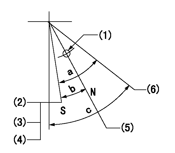
N:Engine manufacturer's normal use
S:Stop the pump.
(1)Use the hole at R = aa
(2)Set the stopper bolt at speed = bb and rack position = cc (non-injection rack position). Confirm non-injection.
(3)After setting the stopper bolt, confirm non-injection at speed dd. Rack position = ee or less (non-injection rack position).
(4)-
(5)Rack position corresponding to ff
(6)Free (at delivery)
----------
aa=40mm bb=1750r/min cc=(6.2)-0.5mm dd=300r/min ee=(8)mm ff=16mm
----------
a=25deg+-5deg b=20deg+-5deg c=35deg+-5deg
----------
aa=40mm bb=1750r/min cc=(6.2)-0.5mm dd=300r/min ee=(8)mm ff=16mm
----------
a=25deg+-5deg b=20deg+-5deg c=35deg+-5deg
0000001501 ACTUATOR
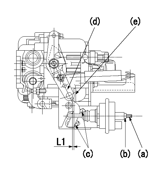
(a) Screw
(B) Nut
Bolt c
(d) Speed lever
(e) Actuator shaft
1. Actuator adjustment procedure
(1)Position the speed lever (d) in the idle position.
(2)Set bolt (c) so that the clearance between the speed lever (d)'s pin and the actuator shaft (e) is approximately L1.
(3)Loosen the nut (b) and fully tighten the screw (a).
(4)Set the pump speed at N1 and read the rack position when negative pressure P1 is applied to the actuator.
(5)Gradually loosen screw (a) and fix the nut (b) when the pump speed is N2 and the rack position is R1.
(6)Apply negative pressure several times and confirm that the lever (d) returns to the idle position at negative pressure '0.'
(7)Confirm that rack position is R2 when negative pressure is P2.
----------
L1=2mm N1=300r/min P1=66.7kPa(500mmHg) N2=500r/min R1=8.6mm P2=66.7kPa(500mmHg) R2=8.6mm
----------
----------
L1=2mm N1=300r/min P1=66.7kPa(500mmHg) N2=500r/min R1=8.6mm P2=66.7kPa(500mmHg) R2=8.6mm
----------
Timing setting

(1)Pump vertical direction
(2)Position of gear mark '3' at No 1 cylinder's beginning of injection
(3)B.T.D.C.: aa
(4)-
----------
aa=9deg
----------
a=(130deg)
----------
aa=9deg
----------
a=(130deg)
Information:
26Feb2020
U-93
A-70
D-86
O-82
Parts stock action only
PRODUCT IMPROVEMENT PROGRAM FOR INSPECTING AND POSSIBLY REMOVING CERTAIN 471-6029 DEF INJECTOR AND MOUNTING GROUPS FROM DEALER PARTS STOCK
108I 7750 PI70799
Caterpillar’s obligations under this Service Letter are subject to, and shall not apply in contravention of, the laws, rules, regulations, directives, ordinances, orders, or statutes of the United States, or of any other applicable jurisdiction, without recourse or liability with respect to Caterpillar.
When submitting claim for Parts Stock Action, Use the appropriate 99Z as the s/n, the appropriate Service Letter Program Number as the Part number in the Part Causing Failure field, "7751" as the Group Number, "56" as the Description Code.
The information supplied in this service letter may not be valid after the termination date of this program.Do not perform the work outlined in this Service Letter after the termination date without first contacting your Caterpillar product analyst.
TERMINATION DATE
31May2020
PROBLEM
A defined batch of existing 471-6029 DEF Injector and Mounting Groups can fail under certain conditions.
ACTION REQUIRED
Inspect all 471-6029 DEF Injector and Mounting Groups in dealer parts stock.
Open the packaging and visually inspect the DEF injector.
If the DEF injector's upper body molding mark is an A or B, then the DEF injector is acceptable to use. Repackage the DEF injector and mark the packaging as inspected per this program and place the part back into dealer parts stock.
If the DEF injector's upper body molding mark is a 1 or 2, then remove the part from dealer parts stock. Refer to the Parts Disposition.
Image 1 shows the molding marks and location.
Image1
SERVICE CLAIM ALLOWANCES
Submit one claim for all parts removed from dealer parts stock.
PARTS DISPOSITION
NACD:
Hold all 471-6029 DEF Injector and Mounting Groups removed from dealer parts stock for a Parts Return Request (PRR). A Parts Return Request (PRR) will be issued to you through the Send-It-Back process after the claim is submitted. Make sure to list the service letter program number on the packing slip and include the closed work order paperwork. Handle all other parts in accordance with your Warranty Bulletin on warranty parts handling.
If a Parts Return Request (PRR) is not issued to you after 30 days through the Send-It-Back process, handle the parts in accordance with your warranty bulletin on warranty parts handling.
EAME, LACD, and APD:
Hold all 471-6029 DEF Injector and Mounting Groups removed from dealer parts stock for 30 days for a possible Parts Return Request (PRR). Make sure to list the service letter program number on the packing slip and include the closed work order paperwork. Handle all other parts in accordance with your Warranty Bulletin on warranty parts handling.
If a Parts Return Request (PRR) is not issued to you after 30 days through the Send-It-Back process, handle the parts in accordance with your warranty bulletin on warranty parts handling.