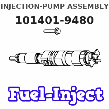
Information injection-pump assembly
ZEXEL
101401-9480
1014019480
Rating:
Cross reference number
ZEXEL
101401-9480
1014019480
Zexel num
Bosch num
Firm num
Name
101401-9480
DPICO
INJECTION-PUMP ASSEMBLY
SH * Q
SH * Q
Calibration Data:
Adjustment conditions
Test oil
1404 Test oil ISO4113 or {SAEJ967d}
1404 Test oil ISO4113 or {SAEJ967d}
Test oil temperature
degC
40
40
45
Nozzle and nozzle holder
105780-8140
Bosch type code
EF8511/9A
Nozzle
105780-0000
Bosch type code
DN12SD12T
Nozzle holder
105780-2080
Bosch type code
EF8511/9
Opening pressure
MPa
17.2
Opening pressure
kgf/cm2
175
Injection pipe
Outer diameter - inner diameter - length (mm) mm 6-2-600
Outer diameter - inner diameter - length (mm) mm 6-2-600
Overflow valve
134424-1420
Overflow valve opening pressure
kPa
157
123
191
Overflow valve opening pressure
kgf/cm2
1.6
1.25
1.95
Tester oil delivery pressure
kPa
157
157
157
Tester oil delivery pressure
kgf/cm2
1.6
1.6
1.6
Direction of rotation (viewed from drive side)
Right R
Right R
Injection timing adjustment
Direction of rotation (viewed from drive side)
Right R
Right R
Injection order
1-3-4-2
Pre-stroke
mm
4.4
4.35
4.45
Beginning of injection position
Drive side NO.1
Drive side NO.1
Difference between angles 1
Cal 1-3 deg. 90 89.5 90.5
Cal 1-3 deg. 90 89.5 90.5
Difference between angles 2
Cal 1-4 deg. 180 179.5 180.5
Cal 1-4 deg. 180 179.5 180.5
Difference between angles 3
Cyl.1-2 deg. 270 269.5 270.5
Cyl.1-2 deg. 270 269.5 270.5
Injection quantity adjustment
Adjusting point
-
Rack position
10.4
Pump speed
r/min
850
850
850
Average injection quantity
mm3/st.
59.5
57.9
61.1
Max. variation between cylinders
%
0
-2.5
2.5
Basic
*
Fixing the rack
*
Standard for adjustment of the maximum variation between cylinders
*
Injection quantity adjustment_02
Adjusting point
H
Rack position
9.5+-0.5
Pump speed
r/min
350
350
350
Average injection quantity
mm3/st.
12
10
14
Max. variation between cylinders
%
0
-14
14
Fixing the rack
*
Standard for adjustment of the maximum variation between cylinders
*
Injection quantity adjustment_03
Adjusting point
A
Rack position
R1(10.4)
Pump speed
r/min
850
850
850
Average injection quantity
mm3/st.
59.5
58.5
60.5
Basic
*
Fixing the lever
*
Injection quantity adjustment_04
Adjusting point
B
Rack position
R1+0.1
Pump speed
r/min
500
500
500
Average injection quantity
mm3/st.
43.6
39.6
47.6
Fixing the lever
*
Injection quantity adjustment_05
Adjusting point
C
Rack position
R1(10.4)
Pump speed
r/min
650
650
650
Average injection quantity
mm3/st.
51
47
55
Fixing the lever
*
Injection quantity adjustment_06
Adjusting point
D
Rack position
R1+0.35
Pump speed
r/min
1600
1600
1600
Average injection quantity
mm3/st.
77
73
81
Fixing the lever
*
Injection quantity adjustment_07
Adjusting point
E
Rack position
(R1-0.1)
Pump speed
r/min
950
950
950
Average injection quantity
mm3/st.
58
54
62
Fixing the lever
*
Injection quantity adjustment_08
Adjusting point
I
Rack position
-
Pump speed
r/min
100
100
100
Average injection quantity
mm3/st.
95
85
105
Fixing the lever
*
Rack limit
*
Timer adjustment
Pump speed
r/min
-
Advance angle
deg.
0
0
0
Remarks
Measure speed (beginning of operation).
Measure speed (beginning of operation).
Timer adjustment_02
Pump speed
r/min
-
Advance angle
deg.
4.5
4
5
Remarks
Measure the actual speed, stop
Measure the actual speed, stop
Test data Ex:
Governor adjustment
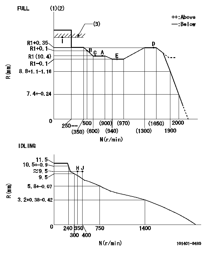
N:Pump speed
R:Rack position (mm)
(1)Torque cam stamping: T1
(2)Tolerance for racks not indicated: +-0.05mm.
(3)RACK LIMIT
----------
T1=K35
----------
----------
T1=K35
----------
Speed control lever angle

F:Full speed
I:Idle
(1)Use the hole at R = aa
(2)Stopper bolt setting
----------
aa=36mm
----------
a=18deg+-5deg b=(38deg)+-3deg
----------
aa=36mm
----------
a=18deg+-5deg b=(38deg)+-3deg
Stop lever angle

N:Pump normal
S:Stop the pump.
----------
----------
a=40deg+-5deg b=40deg+-5deg
----------
----------
a=40deg+-5deg b=40deg+-5deg
Timing setting

(1)Pump vertical direction
(2)Position of gear mark 'CC' at No 1 cylinder's beginning of injection
(3)B.T.D.C.: aa
(4)-
----------
aa=10deg
----------
a=(130deg)
----------
aa=10deg
----------
a=(130deg)
Information:
This Revised Service Letter replaces the 30May2018 Service Letter. Changes have been made to the Parts Needed.
TERMINATION DATE
31May2020
PROBLEM
The DEF injector can become plugged on certain D6N Track-Type Tractors. If the DEF injector becomes plugged it can lead to partial or full blockage of DEF flow.
AFFECTED PRODUCT
Model Identification Number
D6N LGP MG500195-00197, 199-1655
SGG00101-00214
D6N XL GB600100, 200-638
NJN00101-00156
PARTS NEEDED
Qty
Part Number Description
1 4182073 GASKET AS
1 4609257 INJECTOR AS-DEF
1 5457668 SFWR GP-A1000
1 BULK_COOLANT SEE OMM
In order to allow equitable parts availability to all participating dealers, please limit your initial parts order to not exceed 1% of dealership population. This is an initial order recommendation only, and the ultimate responsibility for ordering the total number of parts needed to satisfy the program lies with the dealer.
ACTION REQUIRED
DEF Injector Replacement ? Remove and Install:
Remove DEF injector and replace. Follow Disassembly and Assembly, UENR4079, for DEF Injector and Mounting - Remove and Install.
Update Engine Software:
Reflash the engine controller (ECM) with the software listed in the Parts Needed or latest available on SIS Web.
SERVICE CLAIM ALLOWANCES
Product smu/age whichever comes first Caterpillar Dealer Suggested Customer Suggested
Parts % Labor Hrs% Parts % Labor Hrs% Parts % Labor Hrs%
0-3000 hrs,
0-36 mo 100.0% 100.0% 0.0% 0.0% 0.0% 0.0%
3001-5000 hrs,
37-60 mo 100.0% 0.0% 0.0% 0.0% 0.0% 100.0%
This is a 1.5-hour job
PARTS DISPOSITION
Handle the parts in accordance with your Warranty Bulletin on warranty parts handling.
Have questions with 101401-9480?
Group cross 101401-9480 ZEXEL
Dpico
Mazda
Mazda
Mazda
Mazda
Nissan-Diesel
Dpico
101401-9480
INJECTION-PUMP ASSEMBLY
SH
SH