Information injection-pump assembly
ZEXEL
101401-9453
1014019453
MAZDA
TF6113800D
tf6113800d
Rating:
Service parts 101401-9453 INJECTION-PUMP ASSEMBLY:
1.
_
6.
COUPLING PLATE
7.
COUPLING PLATE
8.
_
9.
_
11.
Nozzle and Holder
TF70 13 H50A
12.
Open Pre:MPa(Kqf/cm2)
19.6{200}

15.
NOZZLE SET
Cross reference number
ZEXEL
101401-9453
1014019453
MAZDA
TF6113800D
tf6113800d
Zexel num
Bosch num
Firm num
Name
Calibration Data:
Adjustment conditions
Test oil
1404 Test oil ISO4113 or {SAEJ967d}
1404 Test oil ISO4113 or {SAEJ967d}
Test oil temperature
degC
40
40
45
Nozzle and nozzle holder
105780-8260
Bosch type code
9 430 610 133
Nozzle
105780-0120
Bosch type code
1 688 901 990
Nozzle holder
105780-2190
Opening pressure
MPa
18
Opening pressure
kgf/cm2
184
Injection pipe
Outer diameter - inner diameter - length (mm) mm 6-2-600
Outer diameter - inner diameter - length (mm) mm 6-2-600
Overflow valve
131425-1020
Overflow valve opening pressure
kPa
255
221
289
Overflow valve opening pressure
kgf/cm2
2.6
2.25
2.95
Tester oil delivery pressure
kPa
255
255
255
Tester oil delivery pressure
kgf/cm2
2.6
2.6
2.6
Direction of rotation (viewed from drive side)
Right R
Right R
Injection timing adjustment
Direction of rotation (viewed from drive side)
Right R
Right R
Injection order
1-3-4-2
Pre-stroke
mm
4.4
4.35
4.45
Beginning of injection position
Drive side NO.1
Drive side NO.1
Difference between angles 1
Cal 1-3 deg. 90 89.5 90.5
Cal 1-3 deg. 90 89.5 90.5
Difference between angles 2
Cal 1-4 deg. 180 179.5 180.5
Cal 1-4 deg. 180 179.5 180.5
Difference between angles 3
Cyl.1-2 deg. 270 269.5 270.5
Cyl.1-2 deg. 270 269.5 270.5
Injection quantity adjustment
Adjusting point
-
Rack position
11.7
Pump speed
r/min
1000
1000
1000
Average injection quantity
mm3/st.
82
81.5
82.5
Max. variation between cylinders
%
0
-2.5
2.5
Basic
*
Fixing the rack
*
Standard for adjustment of the maximum variation between cylinders
*
Injection quantity adjustment_02
Adjusting point
Z
Rack position
9.5+-0.5
Pump speed
r/min
285
285
285
Average injection quantity
mm3/st.
15.3
13.3
17.3
Max. variation between cylinders
%
0
-14
14
Fixing the rack
*
Standard for adjustment of the maximum variation between cylinders
*
Injection quantity adjustment_03
Adjusting point
A
Rack position
R1(11.7)
Pump speed
r/min
1000
1000
1000
Average injection quantity
mm3/st.
82
81.5
82.5
Basic
*
Fixing the lever
*
Injection quantity adjustment_04
Adjusting point
B
Rack position
R1+0.5
Pump speed
r/min
1625
1625
1625
Average injection quantity
mm3/st.
85.5
81.5
89.5
Fixing the lever
*
Injection quantity adjustment_05
Adjusting point
I
Rack position
-
Pump speed
r/min
100
100
100
Average injection quantity
mm3/st.
260
250
270
Fixing the lever
*
Rack limit
*
Timer adjustment
Pump speed
r/min
950--
Advance angle
deg.
0
0
0
Remarks
Start
Start
Timer adjustment_02
Pump speed
r/min
900
Advance angle
deg.
0.5
Timer adjustment_03
Pump speed
r/min
1700
Advance angle
deg.
3.5
3
4
Timer adjustment_04
Pump speed
r/min
-
Advance angle
deg.
5
4.5
5.5
Remarks
Measure the actual speed, stop
Measure the actual speed, stop
Test data Ex:
Governor adjustment
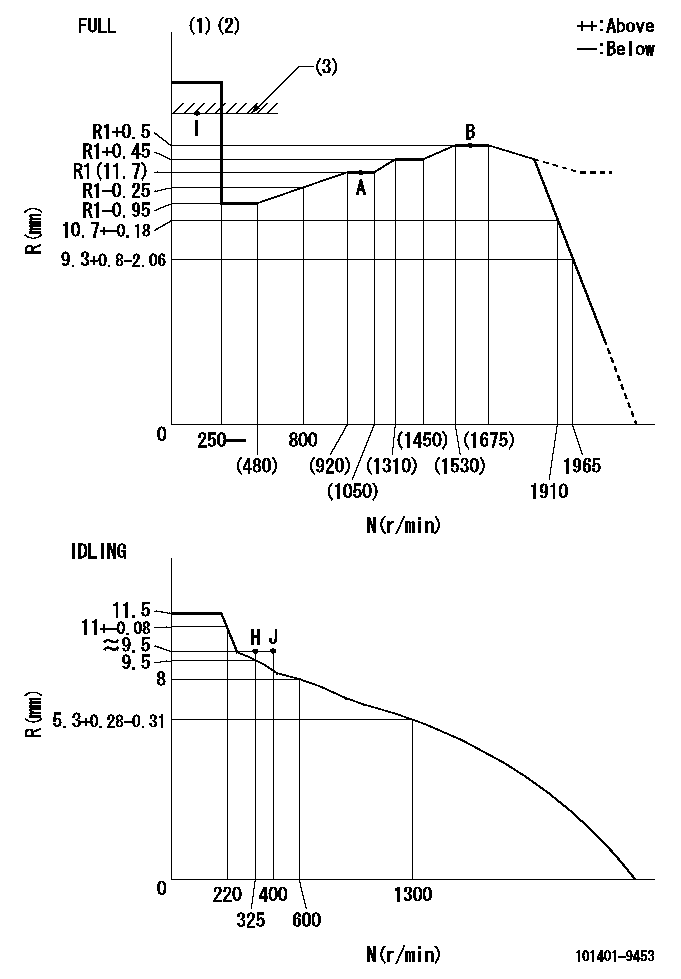
N:Pump speed
R:Rack position (mm)
(1)Torque cam stamping: T1
(2)Tolerance for racks not indicated: +-0.05mm.
(3)RACK LIMIT
----------
T1=L32
----------
----------
T1=L32
----------
Speed control lever angle
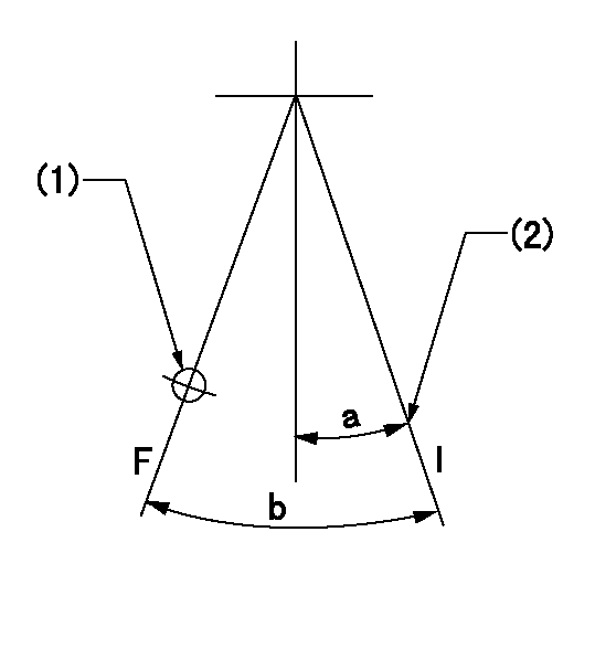
F:Full speed
I:Idle
(1)Use the hole at R = aa
(2)Stopper bolt set position 'H'
----------
aa=36mm
----------
a=20deg+-5deg b=41.5deg+-3deg
----------
aa=36mm
----------
a=20deg+-5deg b=41.5deg+-3deg
Stop lever angle
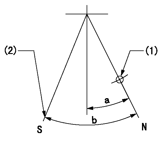
N:Pump normal
S:Stop the pump.
(1)Use the hole at R = aa
(2)Set the stop adjuster screw
----------
aa=39mm
----------
a=14deg+-5deg b=(26deg)+-5deg
----------
aa=39mm
----------
a=14deg+-5deg b=(26deg)+-5deg
0000001501 LEVER
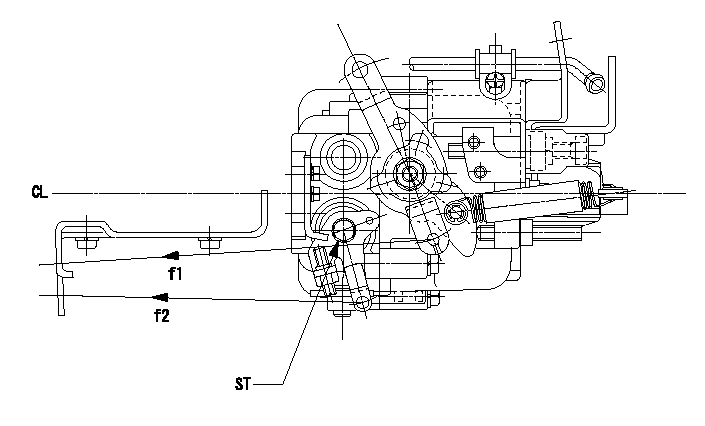
CL:Center line of camshaft
ST:Stop adjuster screw
f1:Direction for pulling the speed lever
f2:Direction for pulling the stop lever
1. Stop lever adjustment outline
(1)After completing all adjustments, confirm that the lever angle is within the specifications in the normal position.
(2)Set the speed lever in the full speed position.
(3)At pump speed Na, position the rack at non-injection position Ra.
(4)Set the stop adjusting screw to fix the speed lever in the idling position.
(5)Confirm that there is no injection at pump speed Nb.
----------
Na=1965r/min Nb=325r/min Ra=6.7+-0.3mm
----------
----------
Na=1965r/min Nb=325r/min Ra=6.7+-0.3mm
----------
Timing setting

(1)Pump vertical direction
(2)Position of gear mark 'CC' at No 1 cylinder's beginning of injection
(3)B.T.D.C.: aa
(4)-
----------
aa=11deg
----------
a=(140deg)
----------
aa=11deg
----------
a=(140deg)
Information:
PARTS DISPOSITION
Handle the parts in accordance with your Warranty Bulletin on warranty parts handling.
Rework Procedure
Diesel Exhaust Fluid Pressure Line Removal Process:
1. Follow the Disassembly and Assembly, UENR4468, for Diesel Exhaust Fluid Lines ? Remove and Install, steps 1 to 9 to remove the DEF pressure line.
2. Remove p-clips (3) and (4) on the plate attached to the hydraulic tank and on the sound wall support leg. Keep the bolt and washer from p-clip (4) as it will be used to install the new pressure line (Image1.1.1).
Image1.1.1
3. Remove p-clip (8) from the inside of the frame and p-clips (10,12) inside of the DEF enclosure from the diesel exhaust fluid pressure line (11) (Image1.2.1).
4. Cut cable ties (9,13) near the PETU from the diesel exhaust fluid pressure line (11) (Image1.2.1).
5. Pull the diesel exhaust fluid pressure line (11) out of the machine (Image1.2.1).
Image1.2.1
After Failure Only, DEF Injector Replacement ? Remove and Install:
1. Remove DEF injector and replace. Follow Disassembly and Assembly, UENR6559, for DEF Injector and Mounting - Remove and Install.
New Diesel Exhaust Fluid Pressure Line Preparation:
1. Lay the 3.65 m pressure line out straight on a flat surface
2. Measure 308 mm from the mating point of the line and the connector and mark the location
3. Measure 631 mm from the mating point of the line and the connector and mark the location
4. Measure 996 mm from the mating point of the line and the connector and mark the location
5. Measure 1386 mm from the mating point of the line and the connector and mark the location
6. Place p-clip (6D-4246) on the line with its edge on the 1st mark
7. Place p-clip (336-8614) on the line with its edge on the 2nd mark
8. Place p-clip (336-8614) on the line with its edge on the 3rd mark
9. Place p-clip (336-8614) on the line with its edge on the 4th mark
Note: Keep lines capped when measuring and placing the p-clips
Image1.4.1
Machine Preparation:
1. Remove bracket (1) from machine. Keep the bolt and washer as it will be used when installing the new pressure line (Image1.5.1).
2. Drill an 11 mm diameter hole in the hood support. Refer to Image1.5.2 for location and Image1.5.3 for dimensions.
3. Remove the bolt and washer on the hydraulic tank support plate and keep as it will be used when installing the new diesel exhaust fluid pressure line (Image1.5.4).
Image1.5.1
Image1.5.2
Image1.5.3
Image1.5.4
Installation Process:
1. Remove plugs from the new diesel exhaust fluid pressure line
2. Attach p-clip 6D-4246 (1) and hose to the newly drilled 11 mm hole in the hood support using hardware nut 344-5675 (qty. 1), washer 8T-4121 (qty. 2), and bolt 8T-4195 (qty. 1). Once attached, the p-clip should be oriented at 15 degrees from vertical pointing downwards. Torque hardware to 55 N*m (Image1.6.1).
Image1.6.1
3. Attach p-clip 336-8614 (2) to the hydraulic tank and secure using the removed hardware (bolt: 8T-4136 and washer: 7X-7729) from step 3 of the machine preparation. Once attached, the p-clip should be oriented at 30 degrees from vertical pointing upwards to maintain the upwards slope of the line towards the hydraulic tank. Torque hardware to 55 N*m once p-clip is oriented correctly (Image1.7.1.).
Image1.7.1
4. Connect the diesel exhaust fluid line to