Information injection-pump assembly
ZEXEL
101401-9450
1014019450
MAZDA
TF6013800A
tf6013800a
Rating:
Cross reference number
ZEXEL
101401-9450
1014019450
MAZDA
TF6013800A
tf6013800a
Zexel num
Bosch num
Firm num
Name
Calibration Data:
Adjustment conditions
Test oil
1404 Test oil ISO4113 or {SAEJ967d}
1404 Test oil ISO4113 or {SAEJ967d}
Test oil temperature
degC
40
40
45
Nozzle and nozzle holder
105780-8260
Bosch type code
9 430 610 133
Nozzle
105780-0120
Bosch type code
1 688 901 990
Nozzle holder
105780-2190
Opening pressure
MPa
18
Opening pressure
kgf/cm2
184
Injection pipe
Outer diameter - inner diameter - length (mm) mm 6-2-600
Outer diameter - inner diameter - length (mm) mm 6-2-600
Overflow valve
131425-1020
Overflow valve opening pressure
kPa
255
221
289
Overflow valve opening pressure
kgf/cm2
2.6
2.25
2.95
Tester oil delivery pressure
kPa
255
255
255
Tester oil delivery pressure
kgf/cm2
2.6
2.6
2.6
Direction of rotation (viewed from drive side)
Right R
Right R
Injection timing adjustment
Direction of rotation (viewed from drive side)
Right R
Right R
Injection order
1-3-4-2
Pre-stroke
mm
4.4
4.35
4.45
Beginning of injection position
Drive side NO.1
Drive side NO.1
Difference between angles 1
Cal 1-3 deg. 90 89.5 90.5
Cal 1-3 deg. 90 89.5 90.5
Difference between angles 2
Cal 1-4 deg. 180 179.5 180.5
Cal 1-4 deg. 180 179.5 180.5
Difference between angles 3
Cyl.1-2 deg. 270 269.5 270.5
Cyl.1-2 deg. 270 269.5 270.5
Injection quantity adjustment
Adjusting point
-
Rack position
11.7
Pump speed
r/min
1000
1000
1000
Average injection quantity
mm3/st.
82
81.5
82.5
Max. variation between cylinders
%
0
-2.5
2.5
Basic
*
Fixing the rack
*
Standard for adjustment of the maximum variation between cylinders
*
Injection quantity adjustment_02
Adjusting point
Z
Rack position
9.5+-0.5
Pump speed
r/min
285
285
285
Average injection quantity
mm3/st.
15.3
13.3
17.3
Max. variation between cylinders
%
0
-14
14
Fixing the rack
*
Standard for adjustment of the maximum variation between cylinders
*
Injection quantity adjustment_03
Adjusting point
A
Rack position
R1(11.7)
Pump speed
r/min
1000
1000
1000
Average injection quantity
mm3/st.
82
81.5
82.5
Basic
*
Fixing the lever
*
Injection quantity adjustment_04
Adjusting point
B
Rack position
R1+0.5
Pump speed
r/min
1625
1625
1625
Average injection quantity
mm3/st.
85.5
81.5
89.5
Fixing the lever
*
Timer adjustment
Pump speed
r/min
950--
Advance angle
deg.
0
0
0
Remarks
Start
Start
Timer adjustment_02
Pump speed
r/min
900
Advance angle
deg.
0.5
Timer adjustment_03
Pump speed
r/min
1700
Advance angle
deg.
3.5
3
4
Timer adjustment_04
Pump speed
r/min
-
Advance angle
deg.
5
4.5
5.5
Remarks
Measure the actual speed, stop
Measure the actual speed, stop
Test data Ex:
Governor adjustment
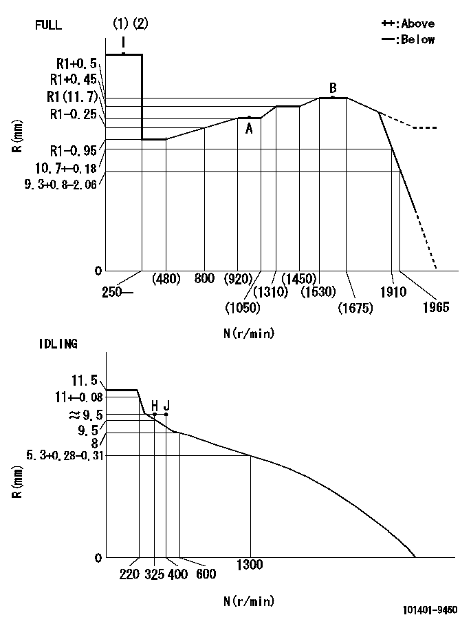
N:Pump speed
R:Rack position (mm)
(1)Torque cam stamping: T1
(2)Tolerances for racks not indicated: +-0.05mm.
----------
T1=L25
----------
----------
T1=L25
----------
Speed control lever angle
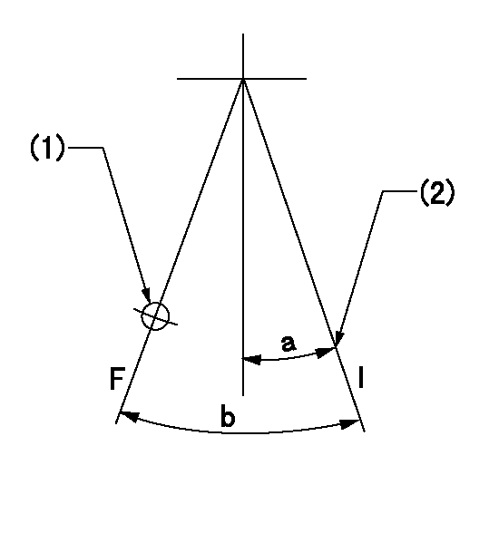
F:Full speed
I:Idle
(1)Use the hole at R = aa
(2)Stopper bolt set position 'H'
----------
aa=36mm
----------
a=20deg+-5deg b=41.5deg+-3deg
----------
aa=36mm
----------
a=20deg+-5deg b=41.5deg+-3deg
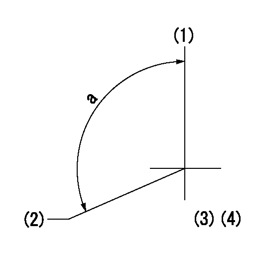
Stop lever angle
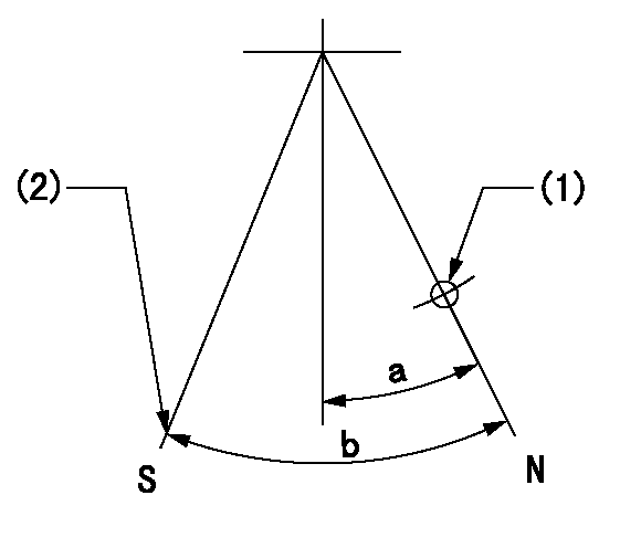
N:Pump normal
S:Stop the pump.
(1)Use the hole at R = aa
(2)Set the stop adjuster screw
----------
aa=39mm
----------
a=14deg+-5deg b=(26deg)+-5deg
----------
aa=39mm
----------
a=14deg+-5deg b=(26deg)+-5deg
0000001501 LEVER
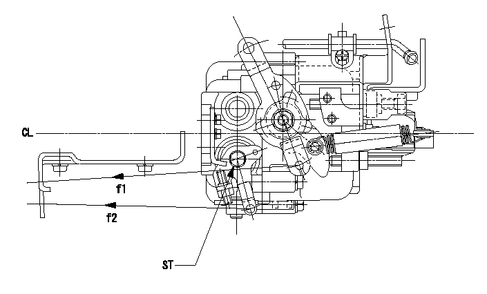
CL:Center line of camshaft
ST:Stop adjuster screw
f1:Direction for pulling the speed lever
f2:Direction for pulling the stop lever
1. Stop lever adjustment outline
(1)After completing all adjustments, confirm that the lever angle is within the specifications in the normal position.
(2)Set the speed lever in the full speed position.
(3)At pump speed Na, position the rack at non-injection position Ra.
(4)Set the stop adjusting screw to fix the speed lever in the idling position.
(5)Confirm that there is no injection at pump speed Nb.
----------
Na=1965r/min Nb=325r/min Ra=6.7+-0.3mm
----------
----------
Na=1965r/min Nb=325r/min Ra=6.7+-0.3mm
----------
Timing setting
(1)Pump vertical direction
(2)Position of gear mark 'CC' at No 1 cylinder's beginning of injection
(3)B.T.D.C.: aa
(4)-
----------
aa=11deg
----------
a=(140deg)
----------
aa=11deg
----------
a=(140deg)
Information:
03May2017
U-247
A-163
D-194
O-200
TM-3
Parts stock action only
PRODUCT IMPROVEMENT PROGRAM FOR INSPECTING AND POSSIBLY REWORKING CERTAIN REMAN FUEL INJECTORS IN DEALER PARTS STOCK
7750 PI70664
Caterpillar’s obligations under this Service Letter are subject to, and shall not apply in contravention of, the laws, rules, regulations, directives, ordinances, orders, or statutes of the United States, or of any other applicable jurisdiction, without recourse or liability with respect to Caterpillar.
When submitting claim for Parts Stock Action, Use the appropriate 99Z as the s/n, the appropriate Service Letter Program Number as the Part number in the Part Causing Failure field, "7751" as the Group Number, "56" as the Description Code.
The information supplied in this service letter may not be valid after the termination date of this program.Do not perform the work outlined in this Service Letter after the termination date without first contacting your Caterpillar product analyst.
TERMINATION DATE
31Aug2017
PROBLEM
Certain Reman fuel injectors were labeled with the same "2755" trim code from January 9, 2017 through April 18, 2017. The injector serial numbers of suspect injectors are 1825569 through 1880788. The trim code may or may not be correct. Image 1 shows a suspect trim code.
Parts from part distribution centers have been inspected and the boxes have been marked with a large green dot to indicate the injector has been inspected, marked correctly, or the trim code is correct. Refer to Image 2.
ACTION REQUIRED
Inspect the following Reman injectors in dealer parts stock:
20R0848
20R0849
20R0850
20R0863
20R0864
20R1264
20R1265
20R1266
20R1268
20R1269
20R1270
20R1271
20R1272
20R1273
20R1274
20R1275
20R1276
20R1277
20R1278
20R1279
20R1280
20R1281
20R1282
20R1283
20R2296
20R3247
20R3477
20R3479
20R3480
20R3483
Inspect the date code on the box.
If the date code on the box is not January 9, 2017 through April 18, 2017, then mark the box as inspected per this program and place the part back in dealer parts stock.
If the date code on the box is January 9, 2017 through April 18, 2017, then inspect the injector trim code.
If the trim code is not "2755", then mark the box as inspected per this program and place the part back in dealer parts stock.
If the trim code is "2755", then inspect the injector serial number using the following inspection and rework the procedure:
Use the following web address and download the spreadsheet file:
https://cat.box.com/s/4fwh9nz0lwguh8vomifxj2rapqjc27e9
Use the downloaded file. Type in the injector serial number to check the trim code. The spreadsheet will return whether the trim code is OK to use, or rework and mark the injector with the correct trim code.
Note: Some injector serial numbers will show "2755" as the correct trim code.
If the trim code is correct (acceptable trim code), record the injector serial number, then mark the box as inspected per this program and place the part back in dealer parts stock.
If the trim code is not correct (rework), the injector must be relabeled. Use an engraving tool to cross out the original trim code and write the correct trim code as shown in Image 3. Record the injector serial number and the updated/corrected trim code, then mark the box as reworked per this program and place the part back in dealer parts stock.
Image1
Image2
Image3
SERVICE CLAIM ALLOWANCES
Submit one claim for all parts inspected and reworked from dealer parts stock.