Information injection-pump assembly
ZEXEL
101401-9340
1014019340
Rating:
Cross reference number
ZEXEL
101401-9340
1014019340
Zexel num
Bosch num
Firm num
Name
101401-9340
DPICO
INJECTION-PUMP ASSEMBLY
4D31T * Q
4D31T * Q
Calibration Data:
Adjustment conditions
Test oil
1404 Test oil ISO4113 or {SAEJ967d}
1404 Test oil ISO4113 or {SAEJ967d}
Test oil temperature
degC
40
40
45
Nozzle and nozzle holder
105780-8140
Bosch type code
EF8511/9A
Nozzle
105780-0000
Bosch type code
DN12SD12T
Nozzle holder
105780-2080
Bosch type code
EF8511/9
Opening pressure
MPa
17.2
Opening pressure
kgf/cm2
175
Injection pipe
Outer diameter - inner diameter - length (mm) mm 6-2-600
Outer diameter - inner diameter - length (mm) mm 6-2-600
Overflow valve
131424-6220
Overflow valve opening pressure
kPa
255
221
289
Overflow valve opening pressure
kgf/cm2
2.6
2.25
2.95
Tester oil delivery pressure
kPa
157
157
157
Tester oil delivery pressure
kgf/cm2
1.6
1.6
1.6
Direction of rotation (viewed from drive side)
Right R
Right R
Injection timing adjustment
Direction of rotation (viewed from drive side)
Right R
Right R
Injection order
1-3-4-2
Pre-stroke
mm
3.6
3.55
3.65
Beginning of injection position
Drive side NO.1
Drive side NO.1
Difference between angles 1
Cal 1-3 deg. 90 89.5 90.5
Cal 1-3 deg. 90 89.5 90.5
Difference between angles 2
Cal 1-4 deg. 180 179.5 180.5
Cal 1-4 deg. 180 179.5 180.5
Difference between angles 3
Cyl.1-2 deg. 270 269.5 270.5
Cyl.1-2 deg. 270 269.5 270.5
Injection quantity adjustment
Adjusting point
-
Rack position
10.5
Pump speed
r/min
1000
1000
1000
Average injection quantity
mm3/st.
54
53
55
Max. variation between cylinders
%
0
-2.5
2.5
Basic
*
Fixing the rack
*
Standard for adjustment of the maximum variation between cylinders
*
Injection quantity adjustment_02
Adjusting point
H
Rack position
9.5+-0.5
Pump speed
r/min
325
325
325
Average injection quantity
mm3/st.
10
8.7
11.3
Max. variation between cylinders
%
0
-15
15
Fixing the rack
*
Standard for adjustment of the maximum variation between cylinders
*
Injection quantity adjustment_03
Adjusting point
A
Rack position
R1(10.5)
Pump speed
r/min
1000
1000
1000
Average injection quantity
mm3/st.
54
53
55
Basic
*
Fixing the lever
*
Boost pressure
kPa
37.3
37.3
Boost pressure
mmHg
280
280
Injection quantity adjustment_04
Adjusting point
B
Rack position
R1+0.3
Pump speed
r/min
1750
1750
1750
Average injection quantity
mm3/st.
68
64
72
Fixing the lever
*
Boost pressure
kPa
37.3
37.3
Boost pressure
mmHg
280
280
Injection quantity adjustment_05
Adjusting point
C
Rack position
R2(R1-0.
6)
Pump speed
r/min
700
700
700
Average injection quantity
mm3/st.
37.5
33.5
41.5
Fixing the lever
*
Boost pressure
kPa
0
0
0
Boost pressure
mmHg
0
0
0
Injection quantity adjustment_06
Adjusting point
D
Rack position
(R2+0.15
)
Pump speed
r/min
500
500
500
Average injection quantity
mm3/st.
28.5
24.5
32.5
Fixing the lever
*
Boost pressure
kPa
0
0
0
Boost pressure
mmHg
0
0
0
Injection quantity adjustment_07
Adjusting point
I
Rack position
-
Pump speed
r/min
100
100
100
Average injection quantity
mm3/st.
67
67
72
Fixing the lever
*
Boost pressure
kPa
0
0
0
Boost pressure
mmHg
0
0
0
Rack limit
*
Boost compensator adjustment
Pump speed
r/min
700
700
700
Rack position
R1-0.6
Boost pressure
kPa
16
14.7
17.3
Boost pressure
mmHg
120
110
130
Boost compensator adjustment_02
Pump speed
r/min
700
700
700
Rack position
R1(10.5)
Boost pressure
kPa
30.7
24
30.7
Boost pressure
mmHg
230
180
230
Timer adjustment
Pump speed
r/min
1500--
Advance angle
deg.
0
0
0
Remarks
Start
Start
Timer adjustment_02
Pump speed
r/min
1450
Advance angle
deg.
0.5
Timer adjustment_03
Pump speed
r/min
1750
Advance angle
deg.
2.5
2
3
Remarks
Finish
Finish
Test data Ex:
Governor adjustment
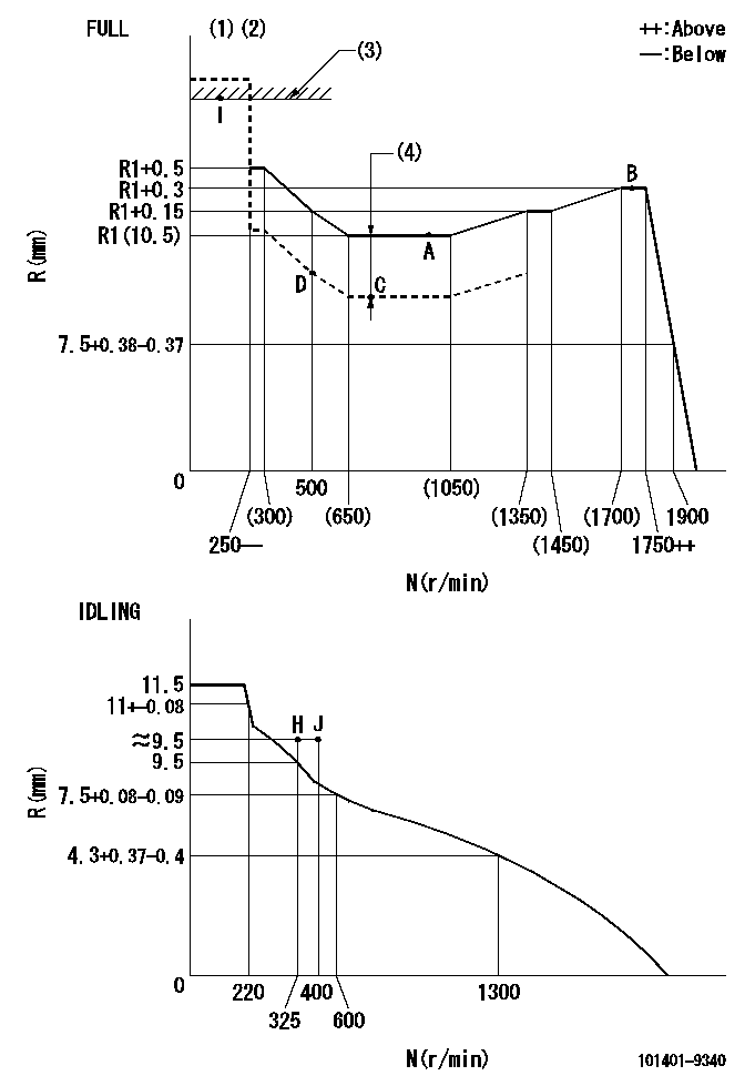
N:Pump speed
R:Rack position (mm)
(1)Torque cam stamping: T1
(2)Tolerance for racks not indicated: +-0.05mm.
(3)RACK LIMIT
(4)Boost compensator stroke: BCL
----------
T1=H93 BCL=0.6+-0.1mm
----------
----------
T1=H93 BCL=0.6+-0.1mm
----------
Speed control lever angle

F:Full speed
I:Idle
(1)Use the hole at R = aa
(2)Stopper bolt set position 'H'
----------
aa=40mm
----------
a=26deg+-5deg b=42deg+-3deg
----------
aa=40mm
----------
a=26deg+-5deg b=42deg+-3deg
Stop lever angle

N:Engine manufacturer's normal use
S:Stop the pump.
(1)Free (at delivery)
(2)Use the hole at R = aa
(3)Rack position corresponding to bb
(4)Set the stopper bolt at speed = cc and rack position = dd (non-injection rack position). Confirm non-injection.
(5)After setting the stopper bolt, confirm non-injection at speed ee. Rack position = ff or less (non-injection rack position).
----------
aa=40mm bb=16mm cc=1700r/min dd=6.5-0.5mm ee=325r/min ff=(8)mm
----------
a=8deg+-5deg b=15deg+-5deg c=25deg+-5deg
----------
aa=40mm bb=16mm cc=1700r/min dd=6.5-0.5mm ee=325r/min ff=(8)mm
----------
a=8deg+-5deg b=15deg+-5deg c=25deg+-5deg
0000001501 ACTUATOR
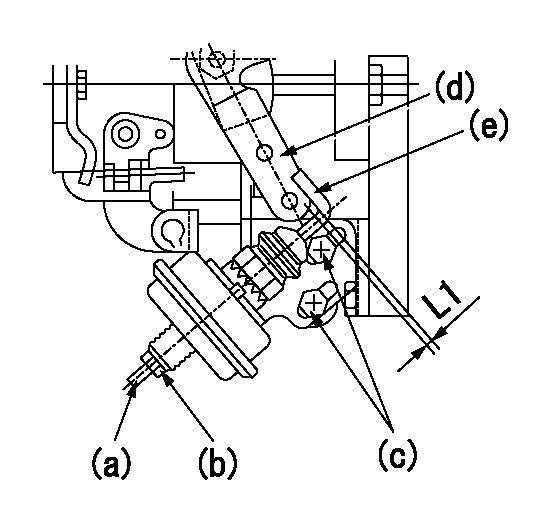
(a) Screw
(B) Nut
Bolt c
(d) Speed lever
(e) Actuator shaft
1. Actuator adjustment procedure
(1)Position the speed lever (d) in the idle position.
(2)Set bolt (c) so that the clearance between the speed lever (d)'s pin and the actuator shaft (e) is approximately L1.
(3)Loosen the nut (b) and fully tighten the screw (a).
(4)Set the pump speed at N1 and read the rack position when negative pressure P1 is applied to the actuator.
(5)Gradually loosen screw (a) and fix the nut (b) when the pump speed is N2 and the rack position is R1.
(6)Apply negative pressure several times and confirm that the lever (d) returns to the idle position at negative pressure '0.'
(7)Confirm that rack position is R2 when negative pressure is P2.
----------
L1=2mm N1=500r/min P1=66.7kPa(500mmHg) N2=500r/min R1=9.1mm P2=66.7kPa(500mmHg) R2=9.1mm
----------
----------
L1=2mm N1=500r/min P1=66.7kPa(500mmHg) N2=500r/min R1=9.1mm P2=66.7kPa(500mmHg) R2=9.1mm
----------
Timing setting

(1)Pump vertical direction
(2)Position of gear mark '3' at No 1 cylinder's beginning of injection
(3)B.T.D.C.: aa
(4)-
----------
aa=14deg
----------
a=(130deg)
----------
aa=14deg
----------
a=(130deg)
Information:
PARTS NEEDED
Qty
Part Number Description
1 6V8260 SEAL-O-RING
1 2147567 SEAL-O-RING-STOR
1 2147568 SEAL-O-RING-STOR
1 2287102 SEAL-O-RING-STOR
1 2842728 SENSOR GP-PRESS
1 2953099 PLUG-SPARK
1 2986488 SENSOR GP-PRESS
1 3003556 VALVE GP-SOL
1 3278044 VALVE GP-CHECK-A
2 3483425 GASKET
1 3790150 PUMP GP-FUEL
1 4154991 VALVE AS-RELIEF
1 4286096 KIT-F PUMP LINE
1 4333677 HEAD AS-COMB
In order to allow equitable parts availability to all participating dealers, please limit your initial parts order to not exceed 31% of dealership population. This is an initial order recommendation only, and the ultimate responsibility for ordering the total number of parts needed to satisfy the program lies with the dealer.
ACTION REQUIRED
1. Refer to Special Instruction, REHS5023, "Replacing the Fuel Injection Pump on Certain C9.3 Engines". Replace the existing 375-5244 common rail fuel injection pump with the 379-0150 common rail fuel injection pump and new gasket 6V-8260. Install a new 356-5214 fuel line from the common rail fuel injection pump to the fuel rail.
2. Refer to C9.3 Disassembly and Assembly, KENR8149 "Engines for Caterpillar Built Machines". Replace the prior 362-0770 common rail pressure relief valve with 415-4991 Pressure Relief Valve, and 228-7102 O-ring.
3. Replace the ARD manifold pilot and main fuel pressure sensors with 284-2728 Main Pressure Sensor and 214-7567 O-ring. Repeat the same procedure with the Pilot Pressure Sensor 298-6488 and 214-7568 O-ring.
4. Replace the 300-3556 Fuel Priming Pump Solenoid and replace the 327-8044 Fuel Priming Pump Check Valve.
5. Replace the existing ARD head with a 433-3677 Combustion Head and (2) 348-3425 Gaskets. Install a new 295-3099 Spark Plug.
SERVICE CLAIM ALLOWANCES
Product smu/age whichever comes first Caterpillar Dealer Suggested Customer Suggested
Parts % Labor Hrs% Parts % Labor Hrs% Parts % Labor Hrs%
0-4000 hrs,
0-24 mo 100.0% 100.0% 0.0% 0.0% 0.0% 0.0%
4001-6000 hrs,
25-36 mo 33.0% 50.0% 0.0% 0.0% 50.0% 50.0%
This is a 26.5-hour job
PARTS DISPOSITION
Handle the parts in accordance with your Warranty Bulletin on warranty parts handling.
Have questions with 101401-9340?
Group cross 101401-9340 ZEXEL
Dpico
101401-9340
INJECTION-PUMP ASSEMBLY
4D31T
4D31T