Information injection-pump assembly
ZEXEL
101401-9255
1014019255
MAZDA
TF3613800G
tf3613800g

Rating:
Cross reference number
ZEXEL
101401-9255
1014019255
MAZDA
TF3613800G
tf3613800g
Zexel num
Bosch num
Firm num
Name
Calibration Data:
Adjustment conditions
Test oil
1404 Test oil ISO4113 or {SAEJ967d}
1404 Test oil ISO4113 or {SAEJ967d}
Test oil temperature
degC
40
40
45
Nozzle and nozzle holder
105780-8140
Bosch type code
EF8511/9A
Nozzle
105780-0000
Bosch type code
DN12SD12T
Nozzle holder
105780-2080
Bosch type code
EF8511/9
Opening pressure
MPa
17.2
Opening pressure
kgf/cm2
175
Injection pipe
Outer diameter - inner diameter - length (mm) mm 6-2-600
Outer diameter - inner diameter - length (mm) mm 6-2-600
Overflow valve
131424-3420
Overflow valve opening pressure
kPa
255
221
289
Overflow valve opening pressure
kgf/cm2
2.6
2.25
2.95
Tester oil delivery pressure
kPa
157
157
157
Tester oil delivery pressure
kgf/cm2
1.6
1.6
1.6
Direction of rotation (viewed from drive side)
Right R
Right R
Injection timing adjustment
Direction of rotation (viewed from drive side)
Right R
Right R
Injection order
1-3-4-2
Pre-stroke
mm
3.3
3.25
3.35
Beginning of injection position
Drive side NO.1
Drive side NO.1
Difference between angles 1
Cal 1-3 deg. 90 89.5 90.5
Cal 1-3 deg. 90 89.5 90.5
Difference between angles 2
Cal 1-4 deg. 180 179.5 180.5
Cal 1-4 deg. 180 179.5 180.5
Difference between angles 3
Cyl.1-2 deg. 270 269.5 270.5
Cyl.1-2 deg. 270 269.5 270.5
Injection quantity adjustment
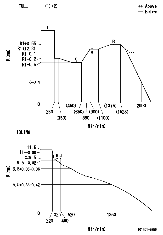
Adjusting point
-
Rack position
12.3
Pump speed
r/min
1000
1000
1000
Average injection quantity
mm3/st.
61.6
61.1
62.1
Max. variation between cylinders
%
0
-2.5
2.5
Basic
*
Fixing the rack
*
Standard for adjustment of the maximum variation between cylinders
*
Injection quantity adjustment_02
Adjusting point
H
Rack position
9.5+-0.5
Pump speed
r/min
325
325
325
Average injection quantity
mm3/st.
14.5
12.5
16.5
Max. variation between cylinders
%
0
-10
10
Fixing the rack
*
Standard for adjustment of the maximum variation between cylinders
*
Injection quantity adjustment_03
Adjusting point
A
Rack position
R1(12.3)
Pump speed
r/min
1000
1000
1000
Average injection quantity
mm3/st.
61.6
61.1
62.1
Basic
*
Fixing the lever
*
Injection quantity adjustment_04
Adjusting point
B
Rack position
R1+0.55
Pump speed
r/min
1450
1450
1450
Average injection quantity
mm3/st.
79.2
75.2
83.2
Fixing the lever
*
Injection quantity adjustment_05
Adjusting point
C
Rack position
R1-0.5
Pump speed
r/min
625
625
625
Average injection quantity
mm3/st.
47
43
51
Fixing the lever
*
Injection quantity adjustment_06
Adjusting point
I
Rack position
-
Pump speed
r/min
100
100
100
Average injection quantity
mm3/st.
160
160
Fixing the lever
*
Timer adjustment
Pump speed
r/min
-
Advance angle
deg.
0
0
0
Remarks
Measure speed (beginning of operation).
Measure speed (beginning of operation).
Timer adjustment_02
Pump speed
r/min
1250
Advance angle
deg.
2
1.5
2.5
Timer adjustment_03
Pump speed
r/min
1540
Advance angle
deg.
5
4.5
5
Remarks
Finish
Finish
Test data Ex:
Governor adjustment
N:Pump speed
R:Rack position (mm)
(1)Torque cam stamping: T1
(2)Tolerance for racks not indicated: +-0.05mm.
----------
T1=J12
----------
----------
T1=J12
----------
Speed control lever angle

F:Full speed
I:Idle
(1)Use the hole at R = aa
(2)Stopper bolt set position 'H'
----------
aa=36mm
----------
a=20deg+-5deg b=(41deg)+-3deg
----------
aa=36mm
----------
a=20deg+-5deg b=(41deg)+-3deg
Stop lever angle
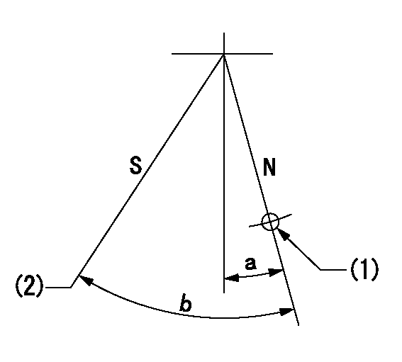
N:Pump normal
S:Stop the pump.
(1)Use the hole at R = aa
(2)Set the stop adjuster screw
----------
aa=39mm
----------
a=14deg+-5deg b=(29.5deg)+-5deg
----------
aa=39mm
----------
a=14deg+-5deg b=(29.5deg)+-5deg
0000001501 LEVER
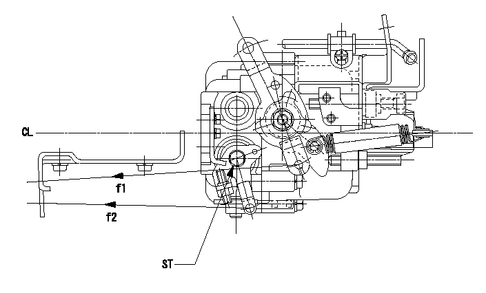
CL:Center line of camshaft
ST:Stop adjuster screw
f1:Direction for pulling the speed lever
f2:Direction for pulling the stop lever
1. Stop lever adjustment outline
(1)After completing all adjustments, confirm that the lever angle is within the specifications in the normal position.
(2)Set the speed lever in the full speed position.
(3)At pump speed Na, position the rack at non-injection position Ra.
(4)Set the stop adjusting screw to fix the speed lever in the idling position.
(5)Confirm that there is no injection at pump speed Nb.
----------
Na=1825r/min Nb=325r/min Ra=4.7+-0.3mm
----------
----------
Na=1825r/min Nb=325r/min Ra=4.7+-0.3mm
----------
0000001601 ACS

(A) Set screw
(B) Push rod 1
(C) Push rod 2
(D) Cover
1. Aneroid compensator unit adjustment
(1)Select the push rod 2 to obtain L2.
(2)Screw in (A) to obtain L1.
2. Adjustment when mounting the governor.
(1)Set the speed of the pump to N1 r/min and fix the control lever at the full set position.
(2)Screw in the aneroid compensator to obtain the performance shown in the graph above.
(3)As there is hysterisis, measure when the absolute pressure drops.
(4)Hysterisis must not exceed rack position = h1.
----------
N1=1000r/min L1=(1.5)mm L2=11+-0.5mm h1=0.15mm
----------
Ra=R1(12.3)mm Rb=R1-0.4mm Pa=88.6+-2.7kPa(665+-20mmHg) Pb=79.4+-0.7kPa(596+-5mmHg) Q1=61.6+-0.5cm3/1000st Q2=(51)+-1cm3/1000st
----------
N1=1000r/min L1=(1.5)mm L2=11+-0.5mm h1=0.15mm
----------
Ra=R1(12.3)mm Rb=R1-0.4mm Pa=88.6+-2.7kPa(665+-20mmHg) Pb=79.4+-0.7kPa(596+-5mmHg) Q1=61.6+-0.5cm3/1000st Q2=(51)+-1cm3/1000st
Timing setting

(1)Pump vertical direction
(2)Position of gear mark 'CC' at No 1 cylinder's beginning of injection
(3)B.T.D.C.: aa
(4)-
----------
aa=7deg
----------
a=(140deg)
----------
aa=7deg
----------
a=(140deg)
Information:
When reporting the repair, use "PS90778" as the Part Number and "7777" as the Group Number. If administered before failure, use "56" as Warranty Claim Description and "T" as the SIMS Description Code. If administered after failure, use "96" as Warranty Claim Description Code and use "Z" as the SIMS Description Code.
The information supplied in this service letter may not be valid after the termination date of this program.Do not perform the work outlined in this Service Letter after the termination date without first contacting your Caterpillar product analyst.
TERMINATION DATE
31Oct2018
PROBLEM
The 341-2378 Injector Wiring Harness may cause an intermittent injector signal that may cause an injector diagnostic code on certain 793F Off-Highway Trucks.
AFFECTED PRODUCT
Model Identification Number
793F SSP01079-01080, 1082-1084, 1161-1165, 1170
PARTS NEEDED
Qty
Part Number Description
16 5L4019 RING-RETAINING
16 0336034 SEAL-O-RING
16 4979351 HARNESS AS
In order to allow equitable parts availability to all participating dealers, please limit your initial parts order to not exceed 11% of dealership population. This is an initial order recommendation only, and the ultimate responsibility for ordering the total number of parts needed to satisfy the program lies with the dealer.
ACTION REQUIRED
Refer to the Service Manual if/as necessary.
Replace the existing 341-2378 Injector Wiring Harness with the a 497-9351 Injector Wiring Harness. The 497-9351 Injector Wiring Harness is distinguishable from the previous harness by a blue zip tie on the harness.
SERVICE CLAIM ALLOWANCES
Product smu/age whichever comes first Caterpillar Dealer Suggested Customer Suggested
Parts % Labor Hrs% Parts % Labor Hrs% Parts % Labor Hrs%
0-11000 hrs,
0-18 mo 100.0% 100.0% 0.0% 0.0% 0.0% 0.0%
This is a 2.0-hour job
If there has been a previous repair, part age/hours will apply. Retain a copy of the previous repair invoice in the dealer's records for audit purposes, and specify repair date and machine hours in the "Additional Comments" section of the warranty claim.
PARTS DISPOSITION
Handle the parts in accordance with your Warranty Bulletin on warranty parts handling.