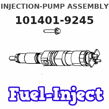
Information injection-pump assembly
ZEXEL
101401-9245
1014019245
MAZDA
TF3513800G
tf3513800g
Rating:
Service parts 101401-9245 INJECTION-PUMP ASSEMBLY:
1.
_
6.
COUPLING PLATE
7.
COUPLING PLATE
8.
_
9.
_
11.
Nozzle and Holder
TF33 13 H50
12.
Open Pre:MPa(Kqf/cm2)
19.6{200}
15.
NOZZLE SET
Cross reference number
ZEXEL
101401-9245
1014019245
MAZDA
TF3513800G
tf3513800g
Zexel num
Bosch num
Firm num
Name
Calibration Data:
Adjustment conditions
Test oil
1404 Test oil ISO4113 or {SAEJ967d}
1404 Test oil ISO4113 or {SAEJ967d}
Test oil temperature
degC
40
40
45
Nozzle and nozzle holder
105780-8140
Bosch type code
EF8511/9A
Nozzle
105780-0000
Bosch type code
DN12SD12T
Nozzle holder
105780-2080
Bosch type code
EF8511/9
Opening pressure
MPa
17.2
Opening pressure
kgf/cm2
175
Injection pipe
Outer diameter - inner diameter - length (mm) mm 6-2-600
Outer diameter - inner diameter - length (mm) mm 6-2-600
Overflow valve
131424-3420
Overflow valve opening pressure
kPa
255
221
289
Overflow valve opening pressure
kgf/cm2
2.6
2.25
2.95
Tester oil delivery pressure
kPa
157
157
157
Tester oil delivery pressure
kgf/cm2
1.6
1.6
1.6
Direction of rotation (viewed from drive side)
Right R
Right R
Injection timing adjustment
Direction of rotation (viewed from drive side)
Right R
Right R
Injection order
1-3-4-2
Pre-stroke
mm
3.3
3.25
3.35
Beginning of injection position
Drive side NO.1
Drive side NO.1
Difference between angles 1
Cal 1-3 deg. 90 89.5 90.5
Cal 1-3 deg. 90 89.5 90.5
Difference between angles 2
Cal 1-4 deg. 180 179.5 180.5
Cal 1-4 deg. 180 179.5 180.5
Difference between angles 3
Cyl.1-2 deg. 270 269.5 270.5
Cyl.1-2 deg. 270 269.5 270.5
Injection quantity adjustment
Adjusting point
-
Rack position
12.3
Pump speed
r/min
1000
1000
1000
Average injection quantity
mm3/st.
61.6
61.1
62.1
Max. variation between cylinders
%
0
-2.5
2.5
Basic
*
Fixing the rack
*
Standard for adjustment of the maximum variation between cylinders
*
Injection quantity adjustment_02
Adjusting point
H
Rack position
9.5+-0.5
Pump speed
r/min
325
325
325
Average injection quantity
mm3/st.
14.5
12.5
16.5
Max. variation between cylinders
%
0
-10
10
Fixing the rack
*
Standard for adjustment of the maximum variation between cylinders
*
Injection quantity adjustment_03
Adjusting point
A
Rack position
R1(12.3)
Pump speed
r/min
1000
1000
1000
Average injection quantity
mm3/st.
61.6
61.1
62.1
Basic
*
Fixing the lever
*
Injection quantity adjustment_04
Adjusting point
B
Rack position
R1+0.55
Pump speed
r/min
1450
1450
1450
Average injection quantity
mm3/st.
79.2
75.2
83.2
Fixing the lever
*
Injection quantity adjustment_05
Adjusting point
C
Rack position
R1-0.5
Pump speed
r/min
625
625
625
Average injection quantity
mm3/st.
47
43
51
Fixing the lever
*
Injection quantity adjustment_06
Adjusting point
I
Rack position
-
Pump speed
r/min
100
100
100
Average injection quantity
mm3/st.
160
160
Fixing the lever
*
Timer adjustment
Pump speed
r/min
-
Advance angle
deg.
0
0
0
Remarks
Measure speed (beginning of operation).
Measure speed (beginning of operation).
Timer adjustment_02
Pump speed
r/min
1250
Advance angle
deg.
2
1.5
2.5
Timer adjustment_03
Pump speed
r/min
1540
Advance angle
deg.
5
4.5
5
Remarks
Finish
Finish
Test data Ex:
Governor adjustment
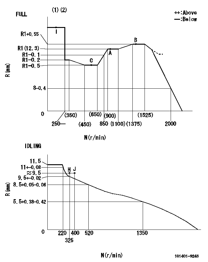
N:Pump speed
R:Rack position (mm)
(1)Torque cam stamping: T1
(2)Tolerance for racks not indicated: +-0.05mm.
----------
T1=J12
----------
----------
T1=J12
----------
Speed control lever angle

F:Full speed
I:Idle
(1)Use the hole at R = aa
(2)Stopper bolt set position 'H'
----------
aa=36mm
----------
a=20deg+-5deg b=(41deg)+-3deg
----------
aa=36mm
----------
a=20deg+-5deg b=(41deg)+-3deg
Stop lever angle
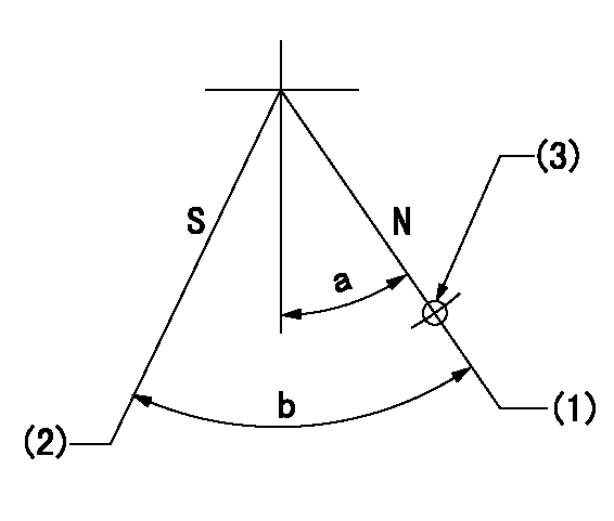
N:Normal
S:Stop
(1)-
(2)Set the stop adjuster screw.
(3)Use the hole at R = aa
----------
aa=39mm
----------
a=14deg+-5deg b=(29.5deg)+-5deg
----------
aa=39mm
----------
a=14deg+-5deg b=(29.5deg)+-5deg
0000001501 LEVER
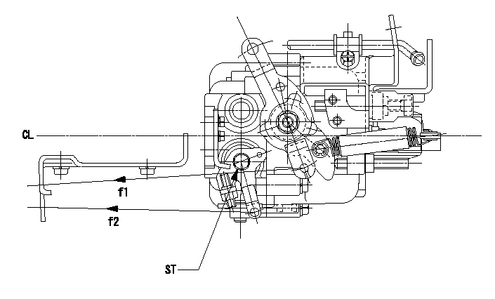
CL:Center line of camshaft
ST:Stop adjuster screw
f1:Direction for pulling the speed lever
f2:Direction for pulling the stop lever
1. Stop lever adjustment outline
(1)After completing all adjustments, confirm that the lever angle is within the specifications in the normal position.
(2)Set the speed lever in the full speed position.
(3)At pump speed Na, position the rack at non-injection position Ra.
(4)Set the stop adjusting screw to fix the speed lever in the idling position.
(5)Confirm that there is no injection at pump speed Nb.
----------
Na=1825r/min Nb=325r/min Ra=4.7+-0.3mm
----------
----------
Na=1825r/min Nb=325r/min Ra=4.7+-0.3mm
----------
Timing setting

(1)Pump vertical direction
(2)Position of gear mark 'CC' at No 1 cylinder's beginning of injection
(3)B.T.D.C.: aa
(4)-
----------
aa=7deg
----------
a=(140deg)
----------
aa=7deg
----------
a=(140deg)
Information:
PARTS NEEDED
Qty
Part Number Description
80 6V5839 WASHER-HARD
80 8T2223 BOLT-SOCKET HD
20 20R5566 INJECTOR GP-F -G
1 SOFTWARE See Note in Action Required
In order to allow equitable parts availability to all participating dealers, please limit your initial parts order to not exceed 32% of dealership population. This is an initial order recommendation only, and the ultimate responsibility for ordering the total number of parts needed to satisfy the program lies with the dealer.
ACTION REQUIRED
****Parts Stock ****
Rework the following engines in dealer parts stock and/or dealer exchange inventory:
797F LAA/HAA
For engine arrangements 2621300, 2822060, 2863503, 3981020, 330-0200, 2863503, 3601647, 3659323, 3659326, 3659327, 3659328, 3659329, 4170588, 188764, 4213013, 4213014, 4233501, 4233502, 20R1363, 20R1494, 20R1495, 20R1496, 20R4668
Service Replacement C175-20 Engines with a LLM, A4K, ZK3, H4N.
Disassemble and replace the former 3315895 or 10R8998 Fuel Injector with the the 20R5566 Fuel Injector in reconditioned or reman engines or the new 4439454 Fuel Injector in new engines in dealer exchange inventory.
Refer to KENR6052-11 R&I Electronic Unit Injector
New engine software is required to support the new fuel injector. Engines must be equipped with the new engine software listed in M0067056.
****Affected Product****
Replace the existing 331-5895 Fuel Injectors or the 10R8998 Fuel Injectors with the new 20R-5566 Fuel Injectors. Refer to the service manual as necessary.
Refer to KENR6052-11 R&I Electronic Unit Injector
Engines must be equipped with the new engine software listed in M0067056.
SERVICE CLAIM ALLOWANCES
****Parts Stock****
Submit one claim for each engine reworked in dealer parts stock. For Reman engine refer to the Parts Needed. For new engines 80 - 6V5839 Washers, 80 - 8T2223 Bolts, 20 - 4439454 Injectors and latest software plus 7 hours of labor will be allowed for each engine that is reworked in dealer parts stock inventory.
Include engine serial number in additional comments field of the claim.
****Affected Product****
Product smu/age whichever comes first Caterpillar Dealer Suggested Customer Suggested
Parts % Labor Hrs% Parts % Labor Hrs% Parts % Labor Hrs%
0-5000 hrs,
0-12 mo 100.0% 100.0% 0.0% 0.0% 0.0% 0.0%
This is a 14.0-hour job
When applicable reasonable travel time and mileage will be allowed.
PARTS DISPOSITION
****Parts Stock****
Handle the parts in accordance with your Warranty Bulletin on warranty parts handling.
****Affected Product****
Handle the parts in accordance with your Warranty Bulletin on warranty parts handling.