Information injection-pump assembly
ZEXEL
101401-9193
1014019193

Rating:
Service parts 101401-9193 INJECTION-PUMP ASSEMBLY:
1.
_
6.
COUPLING PLATE
7.
COUPLING PLATE
8.
_
9.
_
11.
Nozzle and Holder
TF32 13 H50A
12.
Open Pre:MPa(Kqf/cm2)
19.6{200}

15.
NOZZLE SET
Cross reference number
ZEXEL
101401-9193
1014019193
Zexel num
Bosch num
Firm num
Name
101401-9193
INJECTION-PUMP ASSEMBLY
Calibration Data:
Adjustment conditions
Test oil
1404 Test oil ISO4113 or {SAEJ967d}
1404 Test oil ISO4113 or {SAEJ967d}
Test oil temperature
degC
40
40
45
Nozzle and nozzle holder
105780-8140
Bosch type code
EF8511/9A
Nozzle
105780-0000
Bosch type code
DN12SD12T
Nozzle holder
105780-2080
Bosch type code
EF8511/9
Opening pressure
MPa
17.2
Opening pressure
kgf/cm2
175
Injection pipe
Outer diameter - inner diameter - length (mm) mm 6-2-600
Outer diameter - inner diameter - length (mm) mm 6-2-600
Overflow valve
131424-3420
Overflow valve opening pressure
kPa
255
221
289
Overflow valve opening pressure
kgf/cm2
2.6
2.25
2.95
Tester oil delivery pressure
kPa
157
157
157
Tester oil delivery pressure
kgf/cm2
1.6
1.6
1.6
Direction of rotation (viewed from drive side)
Right R
Right R
Injection timing adjustment
Direction of rotation (viewed from drive side)
Right R
Right R
Injection order
1-3-4-2
Pre-stroke
mm
3.3
3.25
3.35
Beginning of injection position
Drive side NO.1
Drive side NO.1
Difference between angles 1
Cal 1-3 deg. 90 89.5 90.5
Cal 1-3 deg. 90 89.5 90.5
Difference between angles 2
Cal 1-4 deg. 180 179.5 180.5
Cal 1-4 deg. 180 179.5 180.5
Difference between angles 3
Cyl.1-2 deg. 270 269.5 270.5
Cyl.1-2 deg. 270 269.5 270.5
Injection quantity adjustment
Adjusting point
-
Rack position
12.7
Pump speed
r/min
1000
1000
1000
Average injection quantity
mm3/st.
66.6
66.1
67.1
Max. variation between cylinders
%
0
-2.5
2.5
Basic
*
Fixing the rack
*
Standard for adjustment of the maximum variation between cylinders
*
Injection quantity adjustment_02
Adjusting point
H
Rack position
9.5+-0.5
Pump speed
r/min
325
325
325
Average injection quantity
mm3/st.
9
7
11
Max. variation between cylinders
%
0
-10
10
Fixing the rack
*
Standard for adjustment of the maximum variation between cylinders
*
Injection quantity adjustment_03
Adjusting point
A
Rack position
R1(12.7)
Pump speed
r/min
1000
1000
1000
Average injection quantity
mm3/st.
66.6
66.1
67.1
Basic
*
Fixing the lever
*
Injection quantity adjustment_04
Adjusting point
C
Rack position
R1-0.4
Pump speed
r/min
625
625
625
Average injection quantity
mm3/st.
49.7
45.7
53.7
Fixing the lever
*
Injection quantity adjustment_05
Adjusting point
I
Rack position
-
Pump speed
r/min
100
100
100
Average injection quantity
mm3/st.
160
160
Fixing the lever
*
Timer adjustment
Pump speed
r/min
700
Advance angle
deg.
0.3
Timer adjustment_02
Pump speed
r/min
1625
Advance angle
deg.
3.8
3.5
4.1
Remarks
Finish
Finish
Test data Ex:
Governor adjustment

N:Pump speed
R:Rack position (mm)
(1)Torque cam stamping: T1
(2)Tolerance for racks not indicated: +-0.05mm.
----------
T1=H12
----------
----------
T1=H12
----------
Speed control lever angle

F:Full speed
I:Idle
(1)Use the hole at R = aa
(2)Stopper bolt setting
----------
aa=36mm
----------
a=20deg+-5deg b=(41deg)+-3deg
----------
aa=36mm
----------
a=20deg+-5deg b=(41deg)+-3deg
Stop lever angle
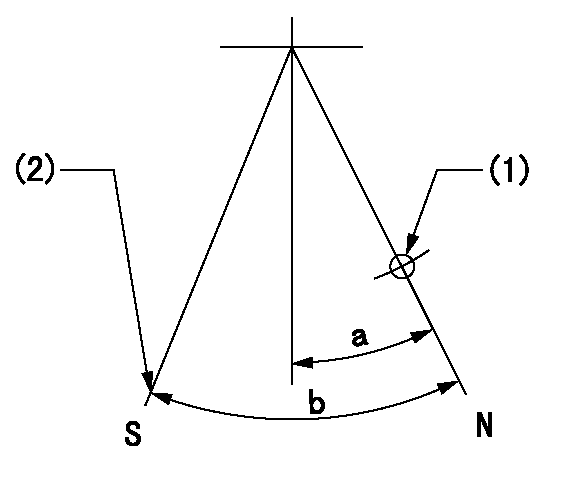
N:Pump normal
S:Engine stop
(1)Use the hole at R = aa
(2)Set the stop adjuster screw
----------
aa=39mm
----------
a=14deg+-5deg b=(29.5deg)+-5deg
----------
aa=39mm
----------
a=14deg+-5deg b=(29.5deg)+-5deg
0000001501 LEVER
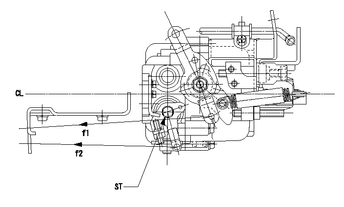
CL:Center line of camshaft
ST:Stop adjuster screw
f1:Direction for pulling the speed lever
f2:Direction for pulling the stop lever
1. Stop lever adjustment outline
(1)After completing all adjustments, confirm that the lever angle is within the specifications in the normal position.
(2)Set the speed lever in the full speed position.
(3)At pump speed Na, position the rack at non-injection position Ra.
(4)Set the stop adjusting screw to fix the speed lever in the idling position.
(5)Confirm that there is no injection at pump speed Nb.
----------
Na=1825r/min Nb=325r/min Ra=4.7+-0.3mm
----------
----------
Na=1825r/min Nb=325r/min Ra=4.7+-0.3mm
----------
Timing setting

(1)Pump vertical direction
(2)Position of gear mark 'CC' at No 1 cylinder's beginning of injection
(3)B.T.D.C.: aa
(4)-
----------
aa=11deg
----------
a=(140deg)
----------
aa=11deg
----------
a=(140deg)
Information:
Start By:a. remove rocker shaft assembliesb. remove turbochargers1. Remove the valve cover bases from the cylinder head. 2. Remove sensor (7) from cylinder head (8). If necessary, remove the O-ring seal from sensor (7).3. Remove bolt and locknut (5).4. Disconnect connector (6).5. Remove bolt (4) and sensor (3). If necessary, remove the O-ring seal from sensor (3).6. Remove three bolts (2) and water lines group (1). 7. Remove bolt (9) from timing advance housing.8. Remove bolt (10) and support (11). 9. Remove the bolt and support (12). Remove the remaining ten bolts and the supports along the intake side of the cylinder head.10. Disconnect hose clamp (13) from the exhaust manifold. 11. Attach Tool (A) and fasten a hoist.12. Remove bolts (14) and remove the cylinder head. The weight of the cylinder head is approximately 172 kg (380 lb).13. Remove the head gasket and the water seals.
Do not put the cylinder head down on a flat surface. Direct injection nozzles extend out from the bottom surface of the cylinder head and will be damaged by the weight of the head.
Install Cylinder Head
1. Thoroughly clean the bottom surface of the cylinder head. Install a new head gasket and water seals. Do not use any adhesives. A new spacer plate gasket must be used when the cylinder head is installed. See the topic "Remove & Install Spacer Plate" in this module. 2. Attach Tool (D) and fasten a hoist.3. Install the cylinder head to the block. The weight of the cylinder head is approximately 172 kg (380 lb).
(1) Large bolts (3/4 inch). Put 6V-4876 Molycoat Paste Lubricant on bolt threads and between washer and underside of bolt heads. (2) Small bolts (3/8 inch). See Step 4h.4. Use the tightening sequence below to tighten the bolts that hold the cylinder head in position. a. Tighten bolts 1 through 14 in number sequence to 270 25 N m (200 20 lb ft).b. Tighten bolts 1 through 14 in number sequence to 470 20 N m (345 15 lb ft).c. Tighten bolts 1 through 14 in number sequence to 470 20 N m (345 15 lb ft).d. Install the rocker arm shafts for the engine valves and the remaining (3/4 in) bolts.e. Tighten bolts 15 through 26 in number sequence to 270 25 N m (200 20 lb ft).f. Tighten bolts 15 through 26 in number sequence to 450 20 N m (330 15 lb ft).g. Tighten bolts 15 through 26 in number sequence to 450 20 N m (330 15 lb ft).h. Tighten the thirteen small bolts (2) to a torque of 45 7 N m (33 5 lb ft). 5. Install support (12).6. Connect hose clamp (13) to exhaust manifold. 7. Install bolt (10) and support (11). Install the remaining ten bolts and the supports along the intake side of the cylinder head. Torque all twelve bolts (10) to 43 7 N m (32 5
Have questions with 101401-9193?
Group cross 101401-9193 ZEXEL
Mazda
101401-9193
INJECTION-PUMP ASSEMBLY