Information injection-pump assembly
BOSCH
F 019 Z10 469
f019z10469
ZEXEL
101401-9151
1014019151
Rating:
Service parts 101401-9151 INJECTION-PUMP ASSEMBLY:
1.
_
6.
COUPLING PLATE
7.
COUPLING PLATE
8.
_
9.
_
11.
Nozzle and Holder
12.
Open Pre:MPa(Kqf/cm2)
18.1(185)

15.
NOZZLE SET
Cross reference number
BOSCH
F 019 Z10 469
f019z10469
ZEXEL
101401-9151
1014019151
Zexel num
Bosch num
Firm num
Name
Calibration Data:
Adjustment conditions
Test oil
1404 Test oil ISO4113 or {SAEJ967d}
1404 Test oil ISO4113 or {SAEJ967d}
Test oil temperature
degC
40
40
45
Nozzle and nozzle holder
105780-8140
Bosch type code
EF8511/9A
Nozzle
105780-0000
Bosch type code
DN12SD12T
Nozzle holder
105780-2080
Bosch type code
EF8511/9
Opening pressure
MPa
17.2
Opening pressure
kgf/cm2
175
Injection pipe
Outer diameter - inner diameter - length (mm) mm 6-2-600
Outer diameter - inner diameter - length (mm) mm 6-2-600
Overflow valve
131424-1520
Overflow valve opening pressure
kPa
157
123
191
Overflow valve opening pressure
kgf/cm2
1.6
1.25
1.95
Tester oil delivery pressure
kPa
157
157
157
Tester oil delivery pressure
kgf/cm2
1.6
1.6
1.6
Direction of rotation (viewed from drive side)
Right R
Right R
Injection timing adjustment
Direction of rotation (viewed from drive side)
Right R
Right R
Injection order
1-3-4-2
Pre-stroke
mm
3.6
3.55
3.65
Beginning of injection position
Drive side NO.1
Drive side NO.1
Difference between angles 1
Cal 1-3 deg. 90 89.5 90.5
Cal 1-3 deg. 90 89.5 90.5
Difference between angles 2
Cal 1-4 deg. 180 179.5 180.5
Cal 1-4 deg. 180 179.5 180.5
Difference between angles 3
Cyl.1-2 deg. 270 269.5 270.5
Cyl.1-2 deg. 270 269.5 270.5
Injection quantity adjustment
Adjusting point
A
Rack position
11.2
Pump speed
r/min
1600
1600
1600
Average injection quantity
mm3/st.
92.2
90.2
94.2
Max. variation between cylinders
%
0
-2.5
2.5
Basic
*
Fixing the lever
*
Injection quantity adjustment_02
Adjusting point
C
Rack position
8.5+-0.5
Pump speed
r/min
300
300
300
Average injection quantity
mm3/st.
8.4
6.9
9.9
Max. variation between cylinders
%
0
-14
14
Fixing the rack
*
Injection quantity adjustment_03
Adjusting point
D
Rack position
-
Pump speed
r/min
100
100
100
Average injection quantity
mm3/st.
94
94
Fixing the lever
*
Remarks
After startup boost setting
After startup boost setting
Timer adjustment
Pump speed
r/min
550--
Advance angle
deg.
0
0
0
Remarks
Start
Start
Timer adjustment_02
Pump speed
r/min
500
Advance angle
deg.
0.5
Timer adjustment_03
Pump speed
r/min
1600
Advance angle
deg.
5
4.5
5.5
Remarks
Finish
Finish
Test data Ex:
Governor adjustment
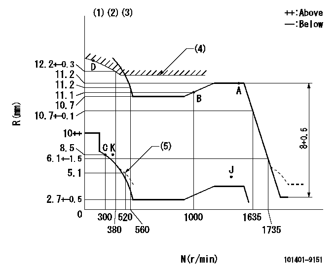
N:Pump speed
R:Rack position (mm)
(1)Lever ratio: RT
(2)Target shim dimension: TH
(3)Tolerance for racks not indicated: +-0.05mm.
(4)Excess fuel setting for starting: SXL (N = N1)
(5)Damper spring setting
----------
RT=1 TH=2.2mm SXL=11.7+-0.1mm N1=500r/min
----------
----------
RT=1 TH=2.2mm SXL=11.7+-0.1mm N1=500r/min
----------
Speed control lever angle

F:Full speed
----------
----------
a=20.5deg+-5deg
----------
----------
a=20.5deg+-5deg
0000000901

F:Full load
I:Idle
(1)Stopper bolt setting
----------
----------
a=16deg+-5deg b=29.5deg+-3deg
----------
----------
a=16deg+-5deg b=29.5deg+-3deg
Stop lever angle
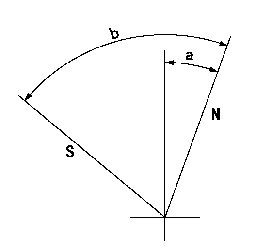
N:Pump normal
S:Stop the pump.
----------
----------
a=20deg+-5deg b=71deg+-5deg
----------
----------
a=20deg+-5deg b=71deg+-5deg
Timing setting

(1)Pump vertical direction
(2)Position of gear mark 'CC' at No 1 cylinder's beginning of injection
(3)B.T.D.C.: aa
(4)-
----------
aa=18deg
----------
a=(90deg)
----------
aa=18deg
----------
a=(90deg)
Information:
Start By:a. remove vibration damper and crankshaft pulley
The crankshaft seal and wear sleeve come as a set and must not be separated from each other at any time. Carefully read Special Instruction, Form No. SMHS8508, that is included with each seal and wear sleeve before any handling of the seal group is made.
1. Use a sharp punch and a hammer to put four equally spaced holes in seal (1).2. Install the tip of Tool (A) into the seal, and use the slide hammer to pull it out of the timing gear housing. Change the location of Tool (A) in the seal in order to pull the seal out evenly. 3. Install 5P-7314 Distorter Ring (3) [part of Tooling (B)] in the space where the seal was removed.
Be careful not to damage the crankshaft surface.
4. Use 5P-7312 Distorter Ring (2) [part of Tooling (B)] to distort the wear sleeve. Put the end of the distorter in the space where the seal was removed.5. Turn the distorter to cause distortion to the wear sleeve. Move the distorter to another position, and turn the distorter again. Do this procedure until the wear sleeve is loose on the crankshaft.6. Remove the distorter, distorter ring and wear sleeve.Install Crankshaft Front Seal & Wear Sleeve
1. Fasten Tooling (A) to the crankshaft.2. Use 6V-1541 Quick Cure Primer to clean the outside diameter of the crankshaft flange and the inside diameter of the wear sleeve.3. Put 9S-3265 Retaining Compound on the outside diameter of the crankshaft flange and the inside diameter of the wear sleeve.
Do not separate the lip-type seal from the wear sleeve. The material in the large lip of the seal can be damaged easily. A scratch or rub (not visible) from a finger can damage the seal enough that it cannot be used. Install the sleeve in the seal. Once there is separation of the sleeve and lip-type seal they cannot be used again and must be replaced with a new seal group. Do not use any type of lubrication during installation of the seal group. If any type of lubrication is used in the installation of the seal group, early seal failure can result.
4. Put seal group (1) in position on Tooling (A). Be sure direction arrows on the seal are the same as crankshaft rotation.5. Put clean engine oil on the face of washer on nut (2) [part of Tooling (B)] that contacts the installer.
The front and rear seals and wear sleeves have different spiral grooves in the seal. Because of this type of design, the front seal group for an engine is different from the rear seal group. If a seal group is installed on the wrong end of the engine, oil can actually be taken out of the engine instead of moving the oil back into the engine.
6. Install Tooling (B) onto Tooling (A), and install nut (2) [part of Tooling (B)] on the threaded shaft of Tooling (A). 7. Tighten nut (2) until Tooling (B) contacts Tooling (A).8.