Information injection-pump assembly
ZEXEL
101401-9080
1014019080
Rating:
Service parts 101401-9080 INJECTION-PUMP ASSEMBLY:
1.
_

6.
COUPLING PLATE
7.
COUPLING PLATE
8.
_
9.
_
11.
Nozzle and Holder
12.
Open Pre:MPa(Kqf/cm2)
21.6{220}

15.
NOZZLE SET
Cross reference number
ZEXEL
101401-9080
1014019080
Zexel num
Bosch num
Firm num
Name
101401-9080
INJECTION-PUMP ASSEMBLY
Calibration Data:
Adjustment conditions
Test oil
1404 Test oil ISO4113 or {SAEJ967d}
1404 Test oil ISO4113 or {SAEJ967d}
Test oil temperature
degC
40
40
45
Nozzle and nozzle holder
105780-8140
Bosch type code
EF8511/9A
Nozzle
105780-0000
Bosch type code
DN12SD12T
Nozzle holder
105780-2080
Bosch type code
EF8511/9
Opening pressure
MPa
17.2
Opening pressure
kgf/cm2
175
Injection pipe
Outer diameter - inner diameter - length (mm) mm 6-2-600
Outer diameter - inner diameter - length (mm) mm 6-2-600
Overflow valve
131424-6220
Overflow valve opening pressure
kPa
255
221
289
Overflow valve opening pressure
kgf/cm2
2.6
2.25
2.95
Tester oil delivery pressure
kPa
157
157
157
Tester oil delivery pressure
kgf/cm2
1.6
1.6
1.6
Direction of rotation (viewed from drive side)
Right R
Right R
Injection timing adjustment
Direction of rotation (viewed from drive side)
Right R
Right R
Injection order
1-3-4-2
Pre-stroke
mm
3.6
3.55
3.65
Beginning of injection position
Drive side NO.1
Drive side NO.1
Difference between angles 1
Cal 1-3 deg. 90 89.5 90.5
Cal 1-3 deg. 90 89.5 90.5
Difference between angles 2
Cal 1-4 deg. 180 179.5 180.5
Cal 1-4 deg. 180 179.5 180.5
Difference between angles 3
Cyl.1-2 deg. 270 269.5 270.5
Cyl.1-2 deg. 270 269.5 270.5
Injection quantity adjustment
Adjusting point
-
Rack position
10.2+-0.
5
Pump speed
r/min
1000
1000
1000
Average injection quantity
mm3/st.
46
45
47
Max. variation between cylinders
%
0
-2.5
2.5
Basic
*
Fixing the rack
*
Standard for adjustment of the maximum variation between cylinders
*
Injection quantity adjustment_02
Adjusting point
-
Rack position
9.7+-0.5
Pump speed
r/min
325
325
325
Average injection quantity
mm3/st.
10
8.7
11.3
Max. variation between cylinders
%
0
-10
10
Fixing the rack
*
Standard for adjustment of the maximum variation between cylinders
*
Remarks
Adjust only variation between cylinders; adjust governor according to governor specifications.
Adjust only variation between cylinders; adjust governor according to governor specifications.
Injection quantity adjustment_03
Adjusting point
A
Rack position
R1(10.2)
Pump speed
r/min
1000
1000
1000
Average injection quantity
mm3/st.
46
45
47
Basic
*
Fixing the lever
*
Boost pressure
kPa
36
36
Boost pressure
mmHg
270
270
Injection quantity adjustment_04
Adjusting point
B
Rack position
R1+0.3
Pump speed
r/min
1750
1750
1750
Average injection quantity
mm3/st.
60
56
64
Fixing the lever
*
Boost pressure
kPa
36
36
Boost pressure
mmHg
270
270
Injection quantity adjustment_05
Adjusting point
C
Rack position
R2(R1-0.
3)
Pump speed
r/min
700
700
700
Average injection quantity
mm3/st.
37.7
33.7
41.7
Fixing the lever
*
Boost pressure
kPa
0
0
0
Boost pressure
mmHg
0
0
0
Injection quantity adjustment_06
Adjusting point
D
Rack position
R2+0.4
Pump speed
r/min
500
500
500
Average injection quantity
mm3/st.
30
26
34
Fixing the lever
*
Boost pressure
kPa
0
0
0
Boost pressure
mmHg
0
0
0
Injection quantity adjustment_07
Adjusting point
I
Rack position
-
Pump speed
r/min
100
100
100
Average injection quantity
mm3/st.
67
67
72
Fixing the lever
*
Rack limit
*
Boost compensator adjustment
Pump speed
r/min
700
700
700
Rack position
R1-0.3
Boost pressure
kPa
20
18.7
21.3
Boost pressure
mmHg
150
140
160
Boost compensator adjustment_02
Pump speed
r/min
700
700
700
Rack position
R1(10.2)
Boost pressure
kPa
29.3
22.6
29.3
Boost pressure
mmHg
220
170
220
Timer adjustment
Pump speed
r/min
1500--
Advance angle
deg.
0
0
0
Load
3/4
Remarks
Start
Start
Timer adjustment_02
Pump speed
r/min
1450
Advance angle
deg.
0.3
Load
3/4
Timer adjustment_03
Pump speed
r/min
1750
Advance angle
deg.
4
3.5
4.5
Load
4/4
Remarks
Finish
Finish
Test data Ex:
Governor adjustment
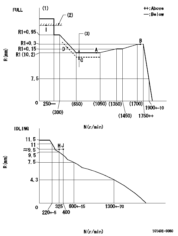
N:Pump speed
R:Rack position (mm)
(1)Torque cam stamping: T1
(2)RACK LIMIT
(3)Boost compensator stroke: BCL
----------
T1=B88 BCL=0.3+-0.1mm
----------
----------
T1=B88 BCL=0.3+-0.1mm
----------
Speed control lever angle

F:Full speed
I:Idle
(1)Use the hole at R = aa
(2)Stopper bolt set position 'H'
----------
aa=40mm
----------
a=26deg+-5deg b=42deg+-3deg
----------
aa=40mm
----------
a=26deg+-5deg b=42deg+-3deg
Stop lever angle

N:Engine manufacturer's normal use
S:Stop the pump.
(1)Free (at shipping)
(2)Use the hole at R = aa
(3)Rack position corresponding to bb
(4)Set the stopper bolt at speed = cc and rack position = dd.
(5)After setting the stopper bolt, confirm non-injection at speed ee. Rack position = ff or less.
----------
aa=40mm bb=16mm cc=1700r/min dd=6.5-0.5mm ee=325r/min ff=8mm
----------
a=8deg+-5deg b=15deg+-5deg c=25deg+-5deg
----------
aa=40mm bb=16mm cc=1700r/min dd=6.5-0.5mm ee=325r/min ff=8mm
----------
a=8deg+-5deg b=15deg+-5deg c=25deg+-5deg
Timing setting

(1)Pump vertical direction
(2)Position of gear mark '3' at No 1 cylinder's beginning of injection
(3)B.T.D.C.: aa
(4)-
----------
aa=11deg
----------
a=(130deg)
----------
aa=11deg
----------
a=(130deg)
Information:
Figure 1The next chart shows maximum acceptable voltage loss in the high current battery circuit feeding the starting motor. These values are maximums for machines of approximately 2000 SMH and up. Newer machines would be less than those shown.
Figure 2Voltages greater than those shown are most often caused by loose and/or corroded connections or defective switch contacts.Diagnosis Procedure
Do not operate the starting motor for more than 30 seconds at a time. After 30 seconds, the cranking must be stopped for two minutes to allow the starting motor to cool. This will prevent damage to the starting motor due to excessive heat buildup.
If the starting motor cranks real slow or does not crank at all, do the following procedure:1. Measure battery voltage at the battery posts with the multimeter while cranking or attempting to crank the engine. Make sure to measure the battery posts. Do not measure the cable post clamps.2. Is battery voltage equal to or greater than shown in Figure 1? a. If the battery voltage is OK, go to Step 3.b. If the battery voltage is too low, test the battery as shown in Special Instruction Form No. SEHS7633. A low battery can be caused by battery condition or a shorted starting motor.3. Measure current draw on the (+) battery cable between the battery and the starting motor solenoid with the clamp-on ammeter. The maximum current draw allowed is shown in Specifications under Load Test. The figures shown in Specifications are taken at temperature of 27°C (80°F). At temperatures below 27°C (80°F), the voltage will be less and the current draw will be higher. If current draw is too much, the starting motor has a problem and must be removed for repair or replacement. If voltage at the battery post is within approximately 2 volts of the lowest value in the applicable temperature range of Figure 1 and if the large starting motor cables get hot, then the starting motor has a problem and the 8T0900 Ammeter test is not needed.4. Measure starting motor voltage from test point (4) to (5) with the multimeter while cranking or attempting to crank the engine.5. Is voltage equal to or greater than shown in Figure 1? a. If the starting motor voltage is OK, the battery and starting motor cables down to the motor are within specifications. Go to Step 8.b. If the starting motor voltage is low, the voltage drop between the battery and the starting motor is too great. Go to Step 6.6. Measure the voltage drops in the cranking circuits with the multimeter. Compare the results with maximum voltage drops allowed in Figure 2.7. Are all the voltages within specifications? a. If the voltage drops are OK, go to Step 8, to check the engine.b. If the voltage drops are too high, repair and/or replace the faulty electrical component.8. Rotate the crankshaft by hand to make sure it is not locked up. Check oil viscosity and any external loads that would affect engine rotation.9. Is the
Have questions with 101401-9080?
Group cross 101401-9080 ZEXEL
Mazda
Mazda
Mazda
Mazda
Mazda
Mitsubishi-Heav
Dpico
101401-9080
INJECTION-PUMP ASSEMBLY