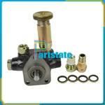
Information injection-pump assembly
BOSCH
9 400 613 775
9400613775
ZEXEL
101401-7570
1014017570
ISUZU
8972033780
8972033780
Rating:
Service parts 101401-7570 INJECTION-PUMP ASSEMBLY:
1.
_
6.
COUPLING PLATE
7.
COUPLING PLATE
8.
_
9.
_
11.
Nozzle and Holder
8-97144-997-1
12.
Open Pre:MPa(Kqf/cm2)
18.1{185}
15.
NOZZLE SET
Cross reference number
BOSCH
9 400 613 775
9400613775
ZEXEL
101401-7570
1014017570
ISUZU
8972033780
8972033780
Zexel num
Bosch num
Firm num
Name
101401-7570
9 400 613 775
8972033780 ISUZU
INJECTION-PUMP ASSEMBLY
4HJ1 K 14BD INJECTION PUMP ASSY PE4AD PE
4HJ1 K 14BD INJECTION PUMP ASSY PE4AD PE
Calibration Data:
Adjustment conditions
Test oil
1404 Test oil ISO4113 or {SAEJ967d}
1404 Test oil ISO4113 or {SAEJ967d}
Test oil temperature
degC
40
40
45
Nozzle and nozzle holder
105780-8140
Bosch type code
EF8511/9A
Nozzle
105780-0000
Bosch type code
DN12SD12T
Nozzle holder
105780-2080
Bosch type code
EF8511/9
Opening pressure
MPa
17.2
Opening pressure
kgf/cm2
175
Injection pipe
Outer diameter - inner diameter - length (mm) mm 6-2-600
Outer diameter - inner diameter - length (mm) mm 6-2-600
Overflow valve
134424-3920
Overflow valve opening pressure
kPa
127
127
127
Overflow valve opening pressure
kgf/cm2
1.3
1.3
1.3
Tester oil delivery pressure
kPa
157
157
157
Tester oil delivery pressure
kgf/cm2
1.6
1.6
1.6
Direction of rotation (viewed from drive side)
Left L
Left L
Injection timing adjustment
Direction of rotation (viewed from drive side)
Left L
Left L
Injection order
1-3-4-2
Pre-stroke
mm
4.1
4.05
4.15
Rack position
Point A R=A
Point A R=A
Beginning of injection position
Governor side NO.1
Governor side NO.1
Difference between angles 1
Cal 1-3 deg. 90 89.5 90.5
Cal 1-3 deg. 90 89.5 90.5
Difference between angles 2
Cal 1-4 deg. 180 179.5 180.5
Cal 1-4 deg. 180 179.5 180.5
Difference between angles 3
Cyl.1-2 deg. 270 269.5 270.5
Cyl.1-2 deg. 270 269.5 270.5
Injection quantity adjustment
Adjusting point
-
Rack position
12.5
Pump speed
r/min
930
930
930
Average injection quantity
mm3/st.
70
68.4
71.6
Max. variation between cylinders
%
0
-4
4
Basic
*
Fixing the rack
*
Standard for adjustment of the maximum variation between cylinders
*
Injection quantity adjustment_02
Adjusting point
H'
Rack position
9.8+-0.5
Pump speed
r/min
315
315
315
Average injection quantity
mm3/st.
10
8.7
11.3
Max. variation between cylinders
%
0
-7
7
Fixing the rack
*
Standard for adjustment of the maximum variation between cylinders
*
Injection quantity adjustment_03
Adjusting point
H
Rack position
9.7+-0.5
Pump speed
r/min
330
330
330
Average injection quantity
mm3/st.
9.5
8.2
10.8
Fixing the rack
*
Injection quantity adjustment_04
Adjusting point
A
Rack position
R1(12.5)
Pump speed
r/min
930
930
930
Average injection quantity
mm3/st.
70
69
71
Basic
*
Fixing the lever
*
Injection quantity adjustment_05
Adjusting point
B
Rack position
R1+0.9
Pump speed
r/min
1550
1550
1550
Average injection quantity
mm3/st.
91.5
87.5
95.5
Fixing the lever
*
Injection quantity adjustment_06
Adjusting point
C
Rack position
R1-0.2
Pump speed
r/min
500
500
500
Average injection quantity
mm3/st.
48.6
44.6
52.6
Fixing the lever
*
Injection quantity adjustment_07
Adjusting point
D
Rack position
R1+0.4
Pump speed
r/min
1240
1240
1240
Average injection quantity
mm3/st.
82
78
86
Fixing the lever
*
Timer adjustment
Pump speed
r/min
-
Advance angle
deg.
0
0
0
Remarks
Measure speed (beginning of operation).
Measure speed (beginning of operation).
Timer adjustment_02
Pump speed
r/min
1550
Remarks
Measure the actual advance angle.
Measure the actual advance angle.
Timer adjustment_03
Pump speed
r/min
-
Advance angle
deg.
6
6
6
Remarks
Measure the actual speed, stop
Measure the actual speed, stop
Test data Ex:
Governor adjustment

N:Pump speed
R:Rack position (mm)
(1)Torque cam stamping: T1
(2)Tolerance for racks not indicated: +-0.05mm.
----------
T1=M59
----------
----------
T1=M59
----------
Speed control lever angle
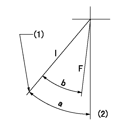
F:Full speed
I:Idle
(1)Set the stopper bolt (rack position = aa, speed = bb).
(2)-
----------
aa=(9.7)mm bb=330r/min
----------
a=36deg+-5deg b=33deg+-3deg
----------
aa=(9.7)mm bb=330r/min
----------
a=36deg+-5deg b=33deg+-3deg
Stop lever angle
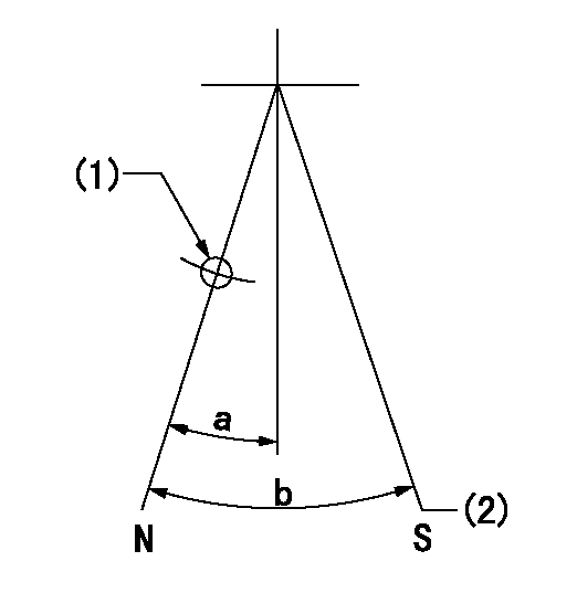
N:Pump normal
S:Stop the pump.
(1)Use the hole at R = aa
(2)At pump speed bb and rack position cc, set the stopper bolt.
----------
aa=58mm bb=1550r/min cc=5+-0.2mm
----------
a=23deg+-5deg b=(29deg)+-5deg
----------
aa=58mm bb=1550r/min cc=5+-0.2mm
----------
a=23deg+-5deg b=(29deg)+-5deg
0000001501 RACK SENSOR
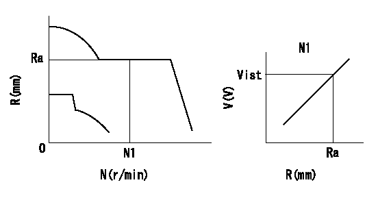
Rack sensor adjustment
1. Flange type rack sensor (rack sensor adjustment -5*20)
(1)These types of rack sensors do not need adjustment. Confirm the performance with the following procedures.
(2)Mount the rack sensor main body to the pump main body.
(3)Fix the pump lever at full.
(4)At supply voltage V1, pump speed N1 and rack position Ra, confirm that the amp's output voltage is Vist.
(5)Move the pump lever two or three times.
(6)Set again to full.
(7)Confirm that the amplifier output voltage is Vist.
(8)Fix the caution plate to the upper part of the rack sensor.
(For those without the caution plate instructions, make sure the nameplate of the rack sensor carries the "Don't hold here" caution.)
(9)Apply red paint to the rack sensor mounting bolts (2 places).
----------
V1=5+-0.01V N1=930r/min Ra=R1(12.5)mm Vist=2.86+-0.28V
----------
----------
V1=5+-0.01V N1=930r/min Ra=R1(12.5)mm Vist=2.86+-0.28V
----------
0000001601 FICD
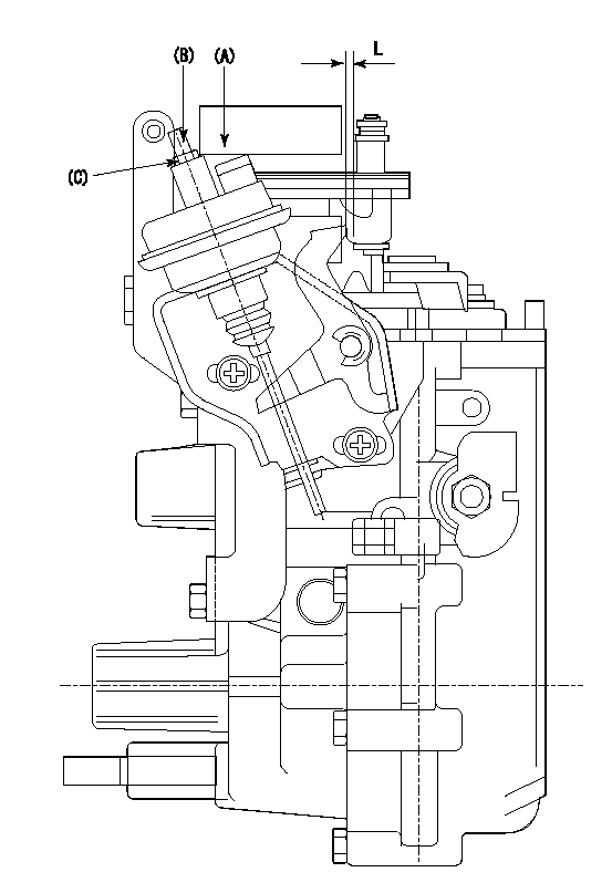
(A) applied negative pressure
(B) Screw
(c) Nut
1. Set the actuator as described below.
(1)Confirm that there is clearance between the actuator lever and the speed lever.
(2)Loosen the nut (C).
(3)Push in the screw (B).
(4)Apply P1 from the actuator (A) part.
(5)Pull out the screw (B) slowly.
(6)Tighten and fix the nut (C) when pump speed is Na and the rack position is Ra.
(7)Torque the nut (C) to T1.
(8)Apply P2 several times.
(9)Confirm that the actuator functions normally.
(10)Confirm that there is a clearance between the actuator lever and the speed lever at that time.
----------
P1=53.3kPa(400mmHg) P2=53.3kPa(400mmHg) Na=430r/min Ra=9.5+-0.1mm T1=1.2~1.6N-m(0.12~0.16kgf-m)
----------
L=(5)mm
----------
P1=53.3kPa(400mmHg) P2=53.3kPa(400mmHg) Na=430r/min Ra=9.5+-0.1mm T1=1.2~1.6N-m(0.12~0.16kgf-m)
----------
L=(5)mm
Timing setting
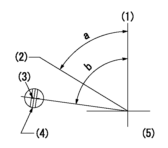
(1)Pump vertical direction
(2)Position of gear's standard threaded hole at No 1 cylinder's beginning of injection
(3)Stamping position on the A/T outer rim
(4)At the No 1 cylinder's beginning of injection, align with the aligning mark seen through the bracket's check hole and mark the A/T's bevel C1.
(5)B.T.D.C.: aa
----------
aa=8.5deg
----------
a=(60deg) b=(85deg)
----------
aa=8.5deg
----------
a=(60deg) b=(85deg)
Information:
Start By:a. remove pistons1. Drain the coolant from the cylinder block.2. Put covers on the journals of the crankshaft for protection from dirt or water. 3. Remove cylinder liners (1) with Tool (A).4. Remove the O-ring seals and filler band from each of the cylinder liners.Install Cylinder Liners
1. Clean cylinder liners (3) and the liner bores in the cylinder block.2. Install the cylinder liners in the block without the O-ring seals or filler bands.3. Check the cylinder liner projection as follows:a. Install the S1589 Bolts (2) and 1S379 Washers of Tool (B) on the cylinder block next to each liner. Tighten the bolts evenly, in four steps: 14 N m (10 lb ft), 35 N m (25 lb ft), 70 N m (52 lb ft) and 95 N m (70 lb ft).b. Put the adapter plate on top of the liner, and install the remainder of Tool (B). Tighten the 1D4595 Bolts (1) evenly in four steps: 7 N m (5 lb ft), 20 N m (15 lb ft), 35 N m (25 lb ft) and 70 N m (52 lb ft).c. Check to be sure the distance from the bottom edge of the crossbar to the top of the cylinder block is the same on both sides of the liner.d. Check the cylinder liner projection with Tool (C) at four locations around the liner.e. Liner projection must be 0.033 to 0.175 mm (.0013 to .0069 in). Measurements on the same liner must not be different by more than 0.05 mm (.002 in). Average measurements between liners next to each other must not be different by more than 0.05 mm (.002 in). The maximum permissible difference between average projection of all cylinder liners is 0.10 mm (.004 in). If the liner is turned in the bore, it can make a difference in the liner projection.4. If the projection is not 0.033 to 0.175 mm (.0013 to .0069 in), check the thickness of the following parts: spacer plate, spacer plate gasket and cylinder liner flange. The thickness of the spacer plate must be 9.970 0.025 mm (.3925 .0010 in). The thickness of the spacer plate gasket must be 0.208 0.025 mm (.0082 .0010 in). The thickness of the cylinder liner flange must be 10.282 0.020 mm (.4048 .0008 in). If the liner projection changes from point to point around the liner, turn the liner to a new position in the bore. If the liner projection is still not to specifications, move the liner to a different bore.5. When the cylinder projection is correct, put an alignment mark on the liner and block so the liner can be installed in the same position from which it was removed. Cylinder liner projection can be adjusted by the removal of material from (machining) the contact face of the cylinder block with the use of the 8S3140 Cylinder Block Counterboring Tool Arrangement. Machine to a minimum depth of 0.76 mm (.030 in) and to a maximum
1. Clean cylinder liners (3) and the liner bores in the cylinder block.2. Install the cylinder liners in the block without the O-ring seals or filler bands.3. Check the cylinder liner projection as follows:a. Install the S1589 Bolts (2) and 1S379 Washers of Tool (B) on the cylinder block next to each liner. Tighten the bolts evenly, in four steps: 14 N m (10 lb ft), 35 N m (25 lb ft), 70 N m (52 lb ft) and 95 N m (70 lb ft).b. Put the adapter plate on top of the liner, and install the remainder of Tool (B). Tighten the 1D4595 Bolts (1) evenly in four steps: 7 N m (5 lb ft), 20 N m (15 lb ft), 35 N m (25 lb ft) and 70 N m (52 lb ft).c. Check to be sure the distance from the bottom edge of the crossbar to the top of the cylinder block is the same on both sides of the liner.d. Check the cylinder liner projection with Tool (C) at four locations around the liner.e. Liner projection must be 0.033 to 0.175 mm (.0013 to .0069 in). Measurements on the same liner must not be different by more than 0.05 mm (.002 in). Average measurements between liners next to each other must not be different by more than 0.05 mm (.002 in). The maximum permissible difference between average projection of all cylinder liners is 0.10 mm (.004 in). If the liner is turned in the bore, it can make a difference in the liner projection.4. If the projection is not 0.033 to 0.175 mm (.0013 to .0069 in), check the thickness of the following parts: spacer plate, spacer plate gasket and cylinder liner flange. The thickness of the spacer plate must be 9.970 0.025 mm (.3925 .0010 in). The thickness of the spacer plate gasket must be 0.208 0.025 mm (.0082 .0010 in). The thickness of the cylinder liner flange must be 10.282 0.020 mm (.4048 .0008 in). If the liner projection changes from point to point around the liner, turn the liner to a new position in the bore. If the liner projection is still not to specifications, move the liner to a different bore.5. When the cylinder projection is correct, put an alignment mark on the liner and block so the liner can be installed in the same position from which it was removed. Cylinder liner projection can be adjusted by the removal of material from (machining) the contact face of the cylinder block with the use of the 8S3140 Cylinder Block Counterboring Tool Arrangement. Machine to a minimum depth of 0.76 mm (.030 in) and to a maximum
Have questions with 101401-7570?
Group cross 101401-7570 ZEXEL
Isuzu
101401-7570
9 400 613 775
8972033780
INJECTION-PUMP ASSEMBLY
4HJ1
4HJ1
