Information injection-pump assembly
ZEXEL
101401-7411
1014017411
Rating:
Cross reference number
ZEXEL
101401-7411
1014017411
Zexel num
Bosch num
Firm num
Name
101401-7411
INJECTION-PUMP ASSEMBLY
Calibration Data:
Adjustment conditions
Test oil
1404 Test oil ISO4113 or {SAEJ967d}
1404 Test oil ISO4113 or {SAEJ967d}
Test oil temperature
degC
40
40
45
Nozzle and nozzle holder
105780-8250
Bosch type code
1 688 901 101
Nozzle
105780-0120
Bosch type code
1 688 901 990
Nozzle holder
105780-2190
Opening pressure
MPa
20.7
Opening pressure
kgf/cm2
211
Injection pipe
Outer diameter - inner diameter - length (mm) mm 6-2-600
Outer diameter - inner diameter - length (mm) mm 6-2-600
Overflow valve
134424-3920
Overflow valve opening pressure
kPa
127
107
147
Overflow valve opening pressure
kgf/cm2
1.3
1.1
1.5
Tester oil delivery pressure
kPa
255
255
255
Tester oil delivery pressure
kgf/cm2
2.6
2.6
2.6
Direction of rotation (viewed from drive side)
Left L
Left L
Injection timing adjustment
Direction of rotation (viewed from drive side)
Left L
Left L
Injection order
1-3-4-2
Pre-stroke
mm
3.8
3.75
3.85
Rack position
Point A R=A
Point A R=A
Beginning of injection position
Governor side NO.1
Governor side NO.1
Difference between angles 1
Cal 1-3 deg. 90 89.5 90.5
Cal 1-3 deg. 90 89.5 90.5
Difference between angles 2
Cal 1-4 deg. 180 179.5 180.5
Cal 1-4 deg. 180 179.5 180.5
Difference between angles 3
Cyl.1-2 deg. 270 269.5 270.5
Cyl.1-2 deg. 270 269.5 270.5
Injection quantity adjustment
Adjusting point
-
Rack position
13.1
Pump speed
r/min
1160
1160
1160
Average injection quantity
mm3/st.
97
95.4
98.6
Max. variation between cylinders
%
0
-4
4
Basic
*
Fixing the rack
*
Standard for adjustment of the maximum variation between cylinders
*
Injection quantity adjustment_02
Adjusting point
Z
Rack position
9.7+-0.5
Pump speed
r/min
285
285
285
Average injection quantity
mm3/st.
14.5
13.2
15.8
Max. variation between cylinders
%
0
-14
14
Fixing the rack
*
Standard for adjustment of the maximum variation between cylinders
*
Injection quantity adjustment_03
Adjusting point
A
Rack position
R1(13.1)
Pump speed
r/min
1160
1160
1160
Average injection quantity
mm3/st.
97
96
98
Basic
*
Fixing the lever
*
Boost pressure
kPa
60
60
Boost pressure
mmHg
450
450
Injection quantity adjustment_04
Adjusting point
B
Rack position
R1+0.35
Pump speed
r/min
1450
1450
1450
Average injection quantity
mm3/st.
96.5
92.5
100.5
Fixing the lever
*
Boost pressure
kPa
60
60
Boost pressure
mmHg
450
450
Injection quantity adjustment_05
Adjusting point
C
Rack position
R2-0.45
Pump speed
r/min
700
700
700
Average injection quantity
mm3/st.
86
82
90
Fixing the lever
*
Boost pressure
kPa
0
0
0
Boost pressure
mmHg
0
0
0
Injection quantity adjustment_06
Adjusting point
I
Rack position
-
Pump speed
r/min
150
150
150
Average injection quantity
mm3/st.
95
95
127
Fixing the lever
*
Boost pressure
kPa
0
0
0
Boost pressure
mmHg
0
0
0
Boost compensator adjustment
Pump speed
r/min
700
700
700
Rack position
R2-0.45
Boost pressure
kPa
27.3
26
28.6
Boost pressure
mmHg
205
195
215
Boost compensator adjustment_02
Pump speed
r/min
700
700
700
Rack position
R2(R1-0.
6)
Boost pressure
kPa
46.7
46.7
46.7
Boost pressure
mmHg
350
350
350
Timer adjustment
Pump speed
r/min
1185--
Advance angle
deg.
0
0
0
Remarks
Start
Start
Timer adjustment_02
Pump speed
r/min
1135
Advance angle
deg.
0.5
Timer adjustment_03
Pump speed
r/min
1450
Advance angle
deg.
4.8
4.3
5.3
Timer adjustment_04
Pump speed
r/min
-
Advance angle
deg.
5
4.5
5.5
Remarks
Measure the actual speed, stop
Measure the actual speed, stop
Test data Ex:
Governor adjustment
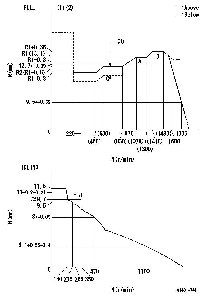
N:Pump speed
R:Rack position (mm)
(1)Torque cam stamping: T1
(2)Tolerance for racks not indicated: +-0.05mm.
(3)Boost compensator stroke: BCL
----------
T1=N23 BCL=0.45+-0.1mm
----------
----------
T1=N23 BCL=0.45+-0.1mm
----------
Speed control lever angle
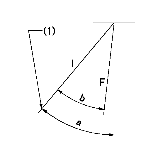
F:Full speed
I:Idle
(1)Stopper bolt set position 'H'
----------
----------
a=42deg+-5deg b=32deg+-3deg
----------
----------
a=42deg+-5deg b=32deg+-3deg
Stop lever angle
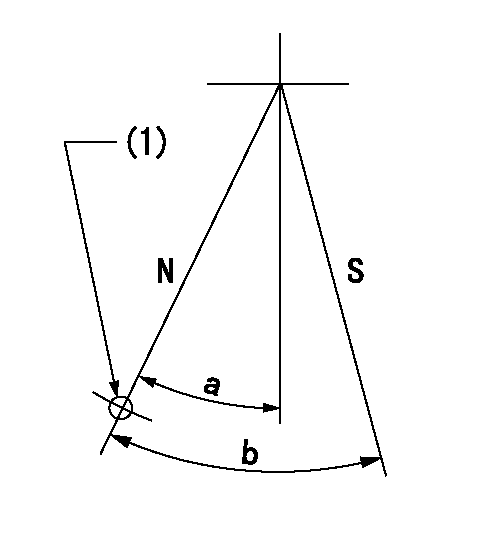
N:Pump normal
S:Stop the pump.
(1)Use the hole at R = aa
----------
aa=64mm
----------
a=20deg+-5deg b=29deg+-5deg
----------
aa=64mm
----------
a=20deg+-5deg b=29deg+-5deg
0000001501 FICD
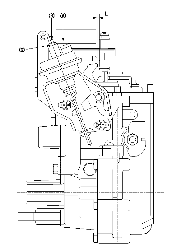
(A) applied negative pressure
(B) Screw
(c) Nut
1. Set the actuator as described below.
(1)Confirm that there is clearance between the actuator lever and the speed lever.
(2)Loosen the nut (C).
(3)Push in the screw (B).
(4)Apply P1 from the actuator (A) part.
(5)Pull out the screw (B) slowly.
(6)Tighten and fix the nut (C) when pump speed is Na and the rack position is Ra.
(7)Torque the nut (C) to T1.
(8)Apply P2 several times.
(9)Confirm that the actuator functions normally.
(10)Confirm that there is a clearance between the actuator lever and the speed lever at that time.
----------
P1=53.3kPa(400mmHg) P2=53.3kPa(400mmHg) Na=410r/min Ra=9.75+-0.1mm T1=1.2~1.6N-m(0.12~0.16kgf-m)
----------
L=(5)mm
----------
P1=53.3kPa(400mmHg) P2=53.3kPa(400mmHg) Na=410r/min Ra=9.75+-0.1mm T1=1.2~1.6N-m(0.12~0.16kgf-m)
----------
L=(5)mm
Timing setting
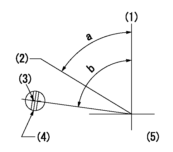
(1)Pump vertical direction
(2)Position of gear's standard threaded hole at No 1 cylinder's beginning of injection
(3)Stamping position on the A/T outer rim
(4)At the No 1 cylinder's beginning of injection, align with the projection seen through the bracket's check hole and mark the A/T's bevel C1.
(5)B.T.D.C.: aa
----------
aa=7deg
----------
a=(60deg) b=(85deg)
----------
aa=7deg
----------
a=(60deg) b=(85deg)
Information:
1. Disconnect air line (1) from the fuel ratio control.2. Remove wire seal (4) from the bolts.3. Remove bolts (3) that hold fuel ratio control (2).4. Remove the fuel ratio control by pulling down and out from the collar. The following steps are for the installation of the fuel ratio control.5. Put fuel ratio control (2) in position on the governor. Make sure the valve head of the fuel ratio control is connected in the groove of the collar.6. Install bolts (3) that hold the fuel ratio control to the governor. Connect air line (1) to the fuel ratio control.7. To make an adjustment to the fuel ratio control, see the topic "Governor Adjustment For The Air Fuel Ratio Control" in, Testing & Adjusting Manual SENR6471.8. Install wire seal (4) on the bolts with Tool (A).Disassemble & Assemble Fuel Ratio Control
Start By:a. remove fuel ratio control 1. Put Tool (A) in a vise so that the station being used is not over the vise jaw. Place the fuel ratio control over the pins in Tool (A). Remove bolts (3) and remove cover (26) and gasket (24).
There is spring force behind cover (7). Hold cover (7) in position, and slowly remove the bolts that hold it to release the spring force.
2. Remove bolts (6). Remove cover (7) from housing (10).3. Remove nut (5) and stop (4) from cover (7).4. Remove spring (8), washer (9) and diaphragm (21) from retainer (25). Remove retainer (25) from housing (10).5. Remove tube (1) from the end of extension (19). Remove nut (2) from extension (19) and remove the extension from retainer (25). Remove valve (16), spring (22) and O-ring seal (23) from the extension.6. Remove spring (20), retainer (18) and spring (17) from housing (10).7. Remove piston (12) and valve assembly (14) from the housing.8. Use Tool (B) and remove snap ring (13) and washer (15) from the valve assembly. Remove piston (12) from the valve assembly.9. Remove seal (11) from piston (12).10. If necessary, remove the stem portion from valve assembly (14).11. Clean and inspect all parts. Make a replacement of all parts that are worn and damaged. The following steps are for the assembly of the fuel ratio control.12. If removed during disassembly, assemble the stem portion of valve assembly (14) on the valve using 9S3265 Retaining Compound.13. Lubricate seal (11) lightly with the lubricant being sealed. Put seal (11) on piston (12) and put piston (12) on valve assembly (14).14. Put washer (15) in position on the valve assembly and use Tool (B) to install snap ring (13) on the valve assembly.15. Place housing (10) on Tool (A), and put Tool (C) into the bore of the housing. Lubricate Tool (C) with clean engine oil.16. Push piston (12) into position with a smooth swift motion. Remove Tool (C) from the housing. Place spring (17), retainer (18) and spring (20) in housing (10).17. Put O-ring seal (23) on extension (19). Put spring (22) and valve (16) in position on the
Have questions with 101401-7411?
Group cross 101401-7411 ZEXEL
Isuzu
101401-7411
INJECTION-PUMP ASSEMBLY