Information injection-pump assembly
ZEXEL
101401-7350
1014017350
ISUZU
8971417480
8971417480

Rating:
Cross reference number
ZEXEL
101401-7350
1014017350
ISUZU
8971417480
8971417480
Zexel num
Bosch num
Firm num
Name
Calibration Data:
Adjustment conditions
Test oil
1404 Test oil ISO4113 or {SAEJ967d}
1404 Test oil ISO4113 or {SAEJ967d}
Test oil temperature
degC
40
40
45
Nozzle and nozzle holder
105780-8140
Bosch type code
EF8511/9A
Nozzle
105780-0000
Bosch type code
DN12SD12T
Nozzle holder
105780-2080
Bosch type code
EF8511/9
Opening pressure
MPa
17.2
Opening pressure
kgf/cm2
175
Injection pipe
Outer diameter - inner diameter - length (mm) mm 6-2-600
Outer diameter - inner diameter - length (mm) mm 6-2-600
Overflow valve
131424-4920
Overflow valve opening pressure
kPa
127
107
147
Overflow valve opening pressure
kgf/cm2
1.3
1.1
1.5
Tester oil delivery pressure
kPa
157
157
157
Tester oil delivery pressure
kgf/cm2
1.6
1.6
1.6
Direction of rotation (viewed from drive side)
Left L
Left L
Injection timing adjustment
Direction of rotation (viewed from drive side)
Left L
Left L
Injection order
1-3-4-2
Pre-stroke
mm
4.1
4.05
4.15
Rack position
Point A R=A
Point A R=A
Beginning of injection position
Governor side NO.1
Governor side NO.1
Difference between angles 1
Cal 1-3 deg. 90 89.5 90.5
Cal 1-3 deg. 90 89.5 90.5
Difference between angles 2
Cal 1-4 deg. 180 179.5 180.5
Cal 1-4 deg. 180 179.5 180.5
Difference between angles 3
Cyl.1-2 deg. 270 269.5 270.5
Cyl.1-2 deg. 270 269.5 270.5
Injection quantity adjustment
Adjusting point
-
Rack position
12.1
Pump speed
r/min
960
960
960
Average injection quantity
mm3/st.
60
58.4
61.6
Max. variation between cylinders
%
0
-4
4
Basic
*
Fixing the rack
*
Standard for adjustment of the maximum variation between cylinders
*
Injection quantity adjustment_02
Adjusting point
H
Rack position
9.8+-0.5
Pump speed
r/min
285
285
285
Average injection quantity
mm3/st.
15.5
14.2
16.8
Max. variation between cylinders
%
0
-10
10
Fixing the rack
*
Standard for adjustment of the maximum variation between cylinders
*
Injection quantity adjustment_03
Adjusting point
A
Rack position
R1(12.1)
Pump speed
r/min
960
960
960
Average injection quantity
mm3/st.
60
59
61
Basic
*
Fixing the lever
*
Injection quantity adjustment_04
Adjusting point
B
Rack position
R1+0.05
Pump speed
r/min
1600
1600
1600
Average injection quantity
mm3/st.
70
66
74
Fixing the lever
*
Injection quantity adjustment_05
Adjusting point
C
Rack position
R1-0.45
Pump speed
r/min
500
500
500
Average injection quantity
mm3/st.
44
40
48
Fixing the lever
*
Timer adjustment
Pump speed
r/min
1050--
Advance angle
deg.
0
0
0
Remarks
Start
Start
Timer adjustment_02
Pump speed
r/min
1000
Advance angle
deg.
0.5
Timer adjustment_03
Pump speed
r/min
1600
Advance angle
deg.
5
4.5
5.5
Remarks
Finish
Finish
Test data Ex:
Governor adjustment
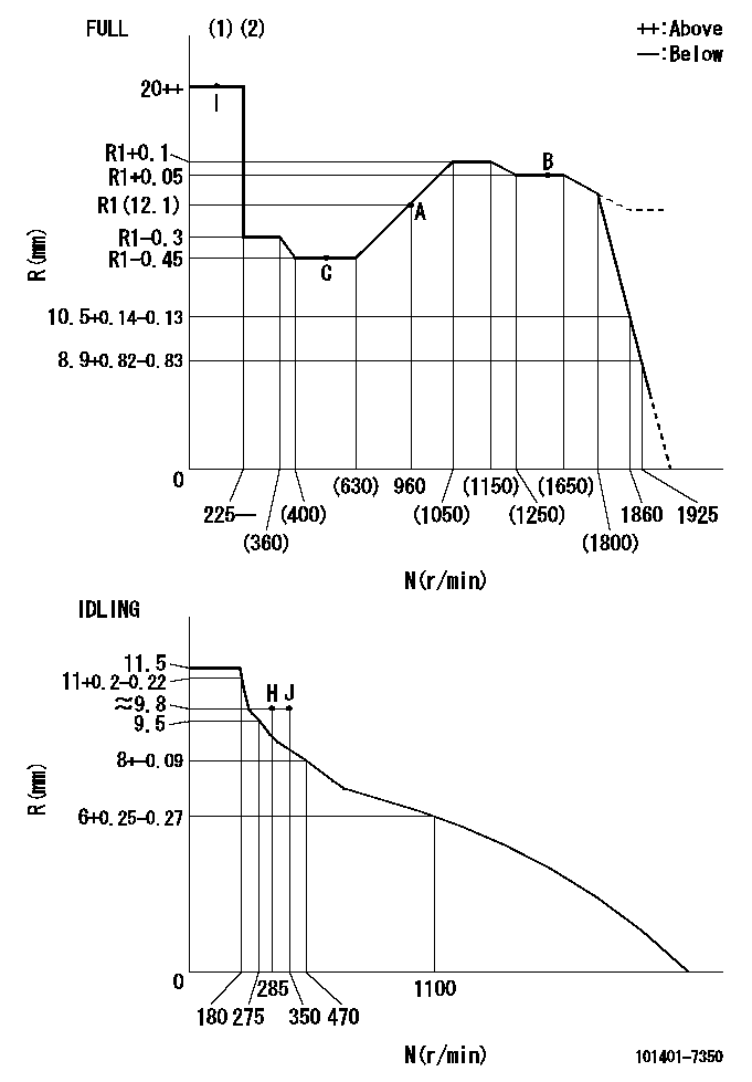
N:Pump speed
R:Rack position (mm)
(1)Torque cam stamping: T1
(2)Tolerance for racks not indicated: +-0.05mm.
----------
T1=L31
----------
----------
T1=L31
----------
Speed control lever angle
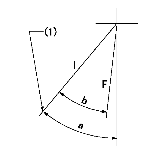
F:Full speed
I:Idle
(1)Stopper bolt set position 'H'
----------
----------
a=41deg+-5deg b=35.5deg+-3deg
----------
----------
a=41deg+-5deg b=35.5deg+-3deg
Stop lever angle
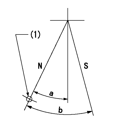
N:Pump normal
S:Stop the pump.
(1)Use the hole at R = aa
----------
aa=64mm
----------
a=20deg+-5deg b=29deg+-5deg
----------
aa=64mm
----------
a=20deg+-5deg b=29deg+-5deg
0000001501 FICD
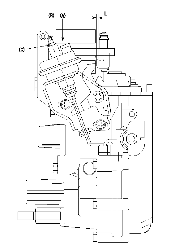
(A) applied negative pressure
(B) Screw
(c) Nut
1. Set the actuator as described below.
(1)Confirm that there is clearance between the actuator lever and the speed lever.
(2)Loosen the nut (C).
(3)Push in the screw (B).
(4)Apply P1 from the actuator (A) part.
(5)Pull out the screw (B) slowly.
(6)Tighten and fix the nut (C) when pump speed is Na and the rack position is Ra.
(7)Torque the nut (C) to T1.
(8)Apply P2 several times.
(9)Confirm that the actuator functions normally.
(10)Confirm that there is a clearance between the actuator lever and the speed lever at that time.
----------
P1=53.3kPa(400mmHg) P2=53.3kPa(400mmHg) Na=400r/min Ra=9.5+-0.1mm T1=1.2~1.6N-m(0.12~0.16kgf-m)
----------
L=(5)mm
----------
P1=53.3kPa(400mmHg) P2=53.3kPa(400mmHg) Na=400r/min Ra=9.5+-0.1mm T1=1.2~1.6N-m(0.12~0.16kgf-m)
----------
L=(5)mm
Timing setting
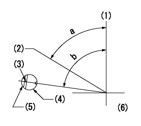
(1)Pump vertical direction
(2)Position of gear's standard threaded hole at No 1 cylinder's beginning of injection
(3)Stamping position on the A/T outer rim
(4)Pump bracket check hole position.
(5)At the No 1 cylinder's beginning of injection, align with the projection seen through the bracket's check hole and mark the A/T's bevel C1.
(6)B.T.D.C.: aa
----------
aa=8deg
----------
a=(60deg) b=(85deg)
----------
aa=8deg
----------
a=(60deg) b=(85deg)
Information:
P-226: Fuel Pressure Sensor Test
The 3176 System monitors fuel pressure with a sensor located at the top of the fuel filter housing. The Fuel Pressure Sensor is supplied with 5.0 volts DC through the ECM Connector (J4/P4, Pin 10). The sensor return line goes through the ECM Connector (J4/P4, Pin 35). Both lines are also common with the Coolant Temperature Sensor. The Fuel Pressure Signal goes to the ECM Connector (J4/P4, Pin 39).Fuel pressure is regulated to a maximum of approximately 550 kPa (80 psi). Step 1. Inspect Connectors And WiringInspect the Fuel Pressure Sensor Connector (J16/P16) and the ECM Connector (J4/P4) and wiring between being sure to: * Check Connector lock rings.* Perform 10 pound pull test on each pin or wire.* Inspect wiring for damage or abrasion.* Inspect connectors for damage or corrosion. Refer to P-201: Inspecting Electrical Connectors for details. Repair any damage, then continue with the next step. Step 2. Check Actual Pressure With GaugeA. Install the 8T0846 Pressure Gauge (0 to 145 psi)(part of 1U5470 Pressure Group) on a "T" fitting with the Fuel Pressure Sensor.B. Start the engine and monitor the fuel pressure at low idle.C. Operate the engine at high idle and check the fuel pressure. Fuel pressure at low idle should be greater than 300 kPa (43.5 psi), and at high idle should be 550 85 kPa (80 12 psi) and remain steady. OK: Fuel pressure is within normal limits. Continue to next step. NOT OK: Fuel pressure is outside normal limits, is erratic or leakage is present. The problem is NOT in the 3176 Electronic Control System. Refer to 3176 Vehicular Diesel Engine, Form No. SENR4964, for Systems Operation, Testing & Adjusting, for help in identifying and repairing the cause of the problem. STOP Step 3. Compare Gauge Reading With ECAP/DDTA. With key OFF, install ECAP/DDT on the 3176 System.B. Start the engine and run at low idle. Compare the gauge reading with the display on the ECAP or DDT and record.C. Operate the engine at high idle. Compare the gauge reading with the display on the ECAP or DDT and record. The ECAP/DDT display should be steady and within 40 kPa (6 psi) of the gauge readings. OK: The Fuel Pressure Sensor is operating correctly. STOP. NOT OK: The ECM is not reading fuel pressure correctly. Continue to next step. Step 4. Check Supply Voltage To SensorA. With key OFF, install the 3-Pin Breakout "T" on the Fuel Pressure Wiring Connector (J16) ONLY. Do not connect to the Fuel Pressure Sensor Connector (P16) at this time.B. Turn key ON (engine off).C. Use the multimeter to measure the voltage between + V, Pin A (J16) and Return, Pin B on the 3-Pin Breakout "T". The voltage should be 5.0 0.5 volts DC. OK: The Fuel Pressure Sensor is receiving the correct voltage. Proceed to Step 7. NOT OK: Supply voltage is not reaching the sensor. Continue to next step. Step 5. Check Supply
The 3176 System monitors fuel pressure with a sensor located at the top of the fuel filter housing. The Fuel Pressure Sensor is supplied with 5.0 volts DC through the ECM Connector (J4/P4, Pin 10). The sensor return line goes through the ECM Connector (J4/P4, Pin 35). Both lines are also common with the Coolant Temperature Sensor. The Fuel Pressure Signal goes to the ECM Connector (J4/P4, Pin 39).Fuel pressure is regulated to a maximum of approximately 550 kPa (80 psi). Step 1. Inspect Connectors And WiringInspect the Fuel Pressure Sensor Connector (J16/P16) and the ECM Connector (J4/P4) and wiring between being sure to: * Check Connector lock rings.* Perform 10 pound pull test on each pin or wire.* Inspect wiring for damage or abrasion.* Inspect connectors for damage or corrosion. Refer to P-201: Inspecting Electrical Connectors for details. Repair any damage, then continue with the next step. Step 2. Check Actual Pressure With GaugeA. Install the 8T0846 Pressure Gauge (0 to 145 psi)(part of 1U5470 Pressure Group) on a "T" fitting with the Fuel Pressure Sensor.B. Start the engine and monitor the fuel pressure at low idle.C. Operate the engine at high idle and check the fuel pressure. Fuel pressure at low idle should be greater than 300 kPa (43.5 psi), and at high idle should be 550 85 kPa (80 12 psi) and remain steady. OK: Fuel pressure is within normal limits. Continue to next step. NOT OK: Fuel pressure is outside normal limits, is erratic or leakage is present. The problem is NOT in the 3176 Electronic Control System. Refer to 3176 Vehicular Diesel Engine, Form No. SENR4964, for Systems Operation, Testing & Adjusting, for help in identifying and repairing the cause of the problem. STOP Step 3. Compare Gauge Reading With ECAP/DDTA. With key OFF, install ECAP/DDT on the 3176 System.B. Start the engine and run at low idle. Compare the gauge reading with the display on the ECAP or DDT and record.C. Operate the engine at high idle. Compare the gauge reading with the display on the ECAP or DDT and record. The ECAP/DDT display should be steady and within 40 kPa (6 psi) of the gauge readings. OK: The Fuel Pressure Sensor is operating correctly. STOP. NOT OK: The ECM is not reading fuel pressure correctly. Continue to next step. Step 4. Check Supply Voltage To SensorA. With key OFF, install the 3-Pin Breakout "T" on the Fuel Pressure Wiring Connector (J16) ONLY. Do not connect to the Fuel Pressure Sensor Connector (P16) at this time.B. Turn key ON (engine off).C. Use the multimeter to measure the voltage between + V, Pin A (J16) and Return, Pin B on the 3-Pin Breakout "T". The voltage should be 5.0 0.5 volts DC. OK: The Fuel Pressure Sensor is receiving the correct voltage. Proceed to Step 7. NOT OK: Supply voltage is not reaching the sensor. Continue to next step. Step 5. Check Supply