Information injection-pump assembly
BOSCH
9 400 613 753
9400613753
ZEXEL
101401-7332
1014017332
ISUZU
8971467830
8971467830
Rating:
Service parts 101401-7332 INJECTION-PUMP ASSEMBLY:
1.
_
6.
COUPLING PLATE
7.
COUPLING PLATE
8.
_
9.
_
11.
Nozzle and Holder
8-97119-812-0
12.
Open Pre:MPa(Kqf/cm2)
18.1{185}
15.
NOZZLE SET
Cross reference number
BOSCH
9 400 613 753
9400613753
ZEXEL
101401-7332
1014017332
ISUZU
8971467830
8971467830
Zexel num
Bosch num
Firm num
Name
101401-7332
9 400 613 753
8971467830 ISUZU
INJECTION-PUMP ASSEMBLY
4HF1 K 14BC INJECTION PUMP ASSY PE4A,5A, PE
4HF1 K 14BC INJECTION PUMP ASSY PE4A,5A, PE
Calibration Data:
Adjustment conditions
Test oil
1404 Test oil ISO4113 or {SAEJ967d}
1404 Test oil ISO4113 or {SAEJ967d}
Test oil temperature
degC
40
40
45
Nozzle and nozzle holder
105780-8140
Bosch type code
EF8511/9A
Nozzle
105780-0000
Bosch type code
DN12SD12T
Nozzle holder
105780-2080
Bosch type code
EF8511/9
Opening pressure
MPa
17.2
Opening pressure
kgf/cm2
175
Injection pipe
Outer diameter - inner diameter - length (mm) mm 6-2-600
Outer diameter - inner diameter - length (mm) mm 6-2-600
Overflow valve
131424-4920
Overflow valve opening pressure
kPa
127
107
147
Overflow valve opening pressure
kgf/cm2
1.3
1.1
1.5
Tester oil delivery pressure
kPa
157
157
157
Tester oil delivery pressure
kgf/cm2
1.6
1.6
1.6
Direction of rotation (viewed from drive side)
Left L
Left L
Injection timing adjustment
Direction of rotation (viewed from drive side)
Left L
Left L
Injection order
1-3-4-2
Pre-stroke
mm
4.1
4.05
4.15
Rack position
Point A R=A
Point A R=A
Beginning of injection position
Governor side NO.1
Governor side NO.1
Difference between angles 1
Cal 1-3 deg. 90 89.5 90.5
Cal 1-3 deg. 90 89.5 90.5
Difference between angles 2
Cal 1-4 deg. 180 179.5 180.5
Cal 1-4 deg. 180 179.5 180.5
Difference between angles 3
Cyl.1-2 deg. 270 269.5 270.5
Cyl.1-2 deg. 270 269.5 270.5
Injection quantity adjustment
Adjusting point
-
Rack position
12
Pump speed
r/min
960
960
960
Average injection quantity
mm3/st.
57
55.4
58.6
Max. variation between cylinders
%
0
-4
4
Basic
*
Fixing the rack
*
Standard for adjustment of the maximum variation between cylinders
*
Injection quantity adjustment_02
Adjusting point
H
Rack position
9.8+-0.5
Pump speed
r/min
285
285
285
Average injection quantity
mm3/st.
15.5
14.2
16.8
Max. variation between cylinders
%
0
-10
10
Fixing the rack
*
Standard for adjustment of the maximum variation between cylinders
*
Injection quantity adjustment_03
Adjusting point
A
Rack position
R1(12)
Pump speed
r/min
960
960
960
Average injection quantity
mm3/st.
57
56
58
Basic
*
Fixing the lever
*
Injection quantity adjustment_04
Adjusting point
B
Rack position
R1+0.1
Pump speed
r/min
1600
1600
1600
Average injection quantity
mm3/st.
68.5
64.5
72.5
Fixing the lever
*
Injection quantity adjustment_05
Adjusting point
C
Rack position
R1-0.2
Pump speed
r/min
500
500
500
Average injection quantity
mm3/st.
45.1
41.1
49.1
Fixing the lever
*
Timer adjustment
Pump speed
r/min
1050--
Advance angle
deg.
0
0
0
Remarks
Start
Start
Timer adjustment_02
Pump speed
r/min
1000
Advance angle
deg.
0.5
Timer adjustment_03
Pump speed
r/min
1600
Advance angle
deg.
5
4.5
5.5
Remarks
Finish
Finish
Test data Ex:
Governor adjustment
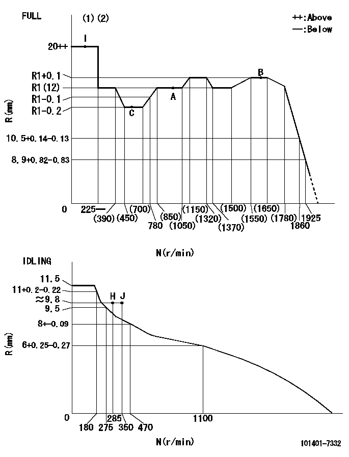
N:Pump speed
R:Rack position (mm)
(1)Torque cam stamping: T1
(2)Tolerance for racks not indicated: +-0.05mm.
----------
T1=L48
----------
----------
T1=L48
----------
Speed control lever angle
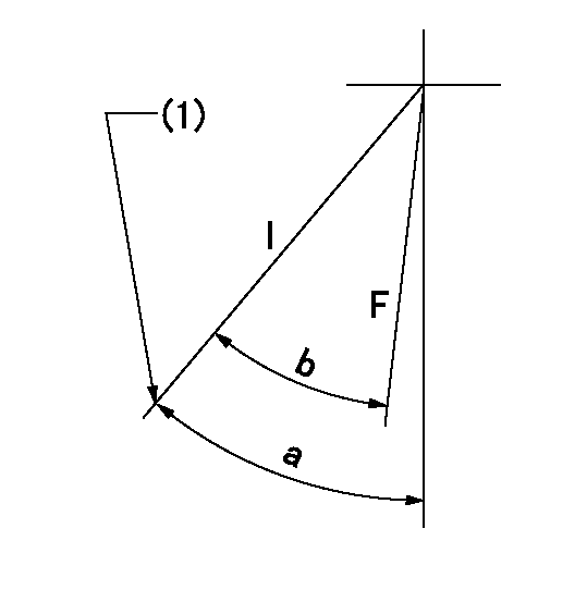
F:Full speed
I:Idle
(1)Stopper bolt set position 'H'
----------
----------
a=41deg+-5deg b=35.5deg+-3deg
----------
----------
a=41deg+-5deg b=35.5deg+-3deg
Stop lever angle
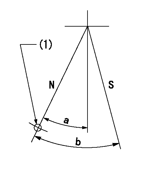
N:Pump normal
S:Stop the pump.
(1)Use the hole at R = aa
----------
aa=64mm
----------
a=20deg+-5deg b=29deg+-5deg
----------
aa=64mm
----------
a=20deg+-5deg b=29deg+-5deg
0000001501 ACS
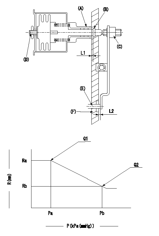
(A) Housing
(B) Snap ring
(C) adjusting screw
(D) Set screw
(E): Push rod
(F) Spacer
1. Adjustment of the aneroid compensator
(1)Adjust with the (D) set screw so that the clearance between the (A) housing and (B) snap ring is L1.
(2)Select the push rod (E) so that the distance from the end surface of the (F) spacer becomes L2.
(3)(C) Turn the screw to adjust the beginning of aneroid compensator operation.
2. Adjustment when mounting the governor.
(1)Set the speed of the pump to N1 r/min and fix the control lever at the full set position.
(2)Adjust using screw C to obtain the performance shown in the graph above.
(3)After final adjustment, confirm that the gap between housing (A) and snapring (B) is L3.
----------
N1=960r/min L1=1.4~1.7mm L2=0.5+-0.5mm L3=0.1~0.5mm
----------
Ra=R1(12)mm Rb=R1-0.4mm Pa=95.4+-5.3kPa(716+-40mmHg) Pb=70.1+-0.7kPa(526+-5mmHg) Q1=57+-1cm3/1000st Q2=(44)+-1.6cm3/1000st
----------
N1=960r/min L1=1.4~1.7mm L2=0.5+-0.5mm L3=0.1~0.5mm
----------
Ra=R1(12)mm Rb=R1-0.4mm Pa=95.4+-5.3kPa(716+-40mmHg) Pb=70.1+-0.7kPa(526+-5mmHg) Q1=57+-1cm3/1000st Q2=(44)+-1.6cm3/1000st
Timing setting
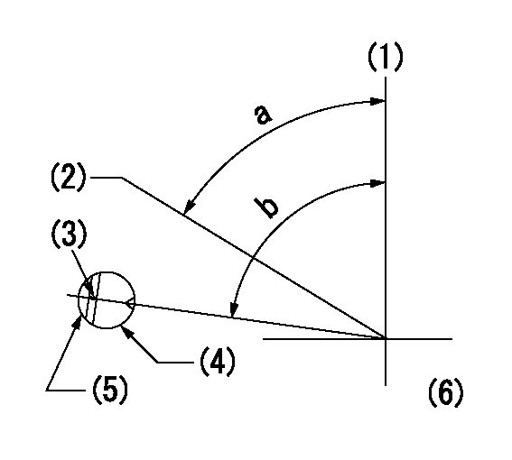
(1)Pump vertical direction
(2)Position of gear's standard threaded hole at No 1 cylinder's beginning of injection
(3)Stamping position on the A/T outer rim
(4)Pump bracket check hole position.
(5)At the No 1 cylinder's beginning of injection, align with the projection seen through the bracket's check hole and mark the A/T's bevel C1.
(6)B.T.D.C.: aa
----------
aa=8deg
----------
a=(60deg) b=(85deg)
----------
aa=8deg
----------
a=(60deg) b=(85deg)
Information:
3176 Electronic Governor Fuel Injection
The ECM controls the amount of fuel injected, by varying signals to the injectors. The injectors will inject fuel ONLY if the injector solenoid is energized. The ECM sends a 100 volt signal to the solenoid to energize it. By controlling the timing and duration of the 100 volt signal, the ECM can control injection timing and the amount of fuel injected.The ECM sets certain limits on the amount of fuel that can be injected. "FRC Fuel Pos" is a limit based on boost pressure to control the fuel-air ratio, for emissions control purposes. When the ECM senses a higher boost pressure (more air into cylinder), it increases the "FRC Fuel Pos" limit (allows more fuel into cylinder). "Rated Fuel Pos" is a limit based on the horsepower rating of the engine. It is similar to the rack stops and torque spring on a mechanically-governed engine. It provides horsepower and torque curves for a specific engine family and rating. All of these limits are programmed by the factory into the Personality Module and are not programmable in the field.Injection timing depends on engine rpm, load and other operation factors. The ECM knows where top-dead-center of cylinder number one is from the signal provided by the engine Speed/Timing Sensor. It decides when injection should occur relative to top-dead-center and provides the signal to the injector at the desired time.Under certain conditions, the 3176 Engine may intentionally operate on just three cylinders. This feature is called "Three Cylinder Cutout" and occurs when the engine is operated under no load, at high rpm (when signals to the injectors are of very short duration). Under these conditions, the ECM does not inject fuel into cylinders 4, 5 and 6. This allows for more precise fuel metering to cylinders 1, 2 and 3. The accompanying change in feel and sound of the engine should not be misdiagnosed as an engine problem. When more power is needed, all six cylinders will be fueled and full power delivered.Programmable Parameters
Certain parameters that affect 3176 Vehicular Diesel Engine operation may be changed through electronic service tools (either the ECAP or DDT). The parameters are stored in the ECM and passwords are used to prevent unauthorized changes.Password protected parameters are either "System Configuration Parameters" or "Customer Specified Parameters". System Configuration Parameters are set at the factory and affect emissions or horsepower ratings within a family of engines. Factory passwords must be obtained and used to change System Configuration Parameters. Customer Specified Parameters are variable and can be used to affect such things as the rpm/horsepower ratings within the limits set by the factory. Customer Passwords must be used to change Customer Specified Parameters.If the operator has not had adequate training, some parameters may affect engine operation in ways that are not expected. This may lead to power or performance complaints, even though the engine is operating correctly.Passwords
"System Configuration Parameters" are protected by factory passwords. System Configuration Parameters are those that affect horsepower family or
Have questions with 101401-7332?
Group cross 101401-7332 ZEXEL
Isuzu
Nissan
Isuzu
Nissan
Isuzu
Isuzu
Isuzu
Isuzu
101401-7332
9 400 613 753
8971467830
INJECTION-PUMP ASSEMBLY
4HF1
4HF1
