Information injection-pump assembly
BOSCH
9 400 613 750
9400613750
ZEXEL
101401-7295
1014017295
ISUZU
8971467781
8971467781

Rating:
Service parts 101401-7295 INJECTION-PUMP ASSEMBLY:
1.
_
6.
COUPLING PLATE
7.
COUPLING PLATE
8.
_
9.
_
11.
Nozzle and Holder
12.
Open Pre:MPa(Kqf/cm2)
17.7(180)
15.
NOZZLE SET
Cross reference number
BOSCH
9 400 613 750
9400613750
ZEXEL
101401-7295
1014017295
ISUZU
8971467781
8971467781
Zexel num
Bosch num
Firm num
Name
101401-7295
9 400 613 750
8971467781 ISUZU
INJECTION-PUMP ASSEMBLY
4HE1-T K
4HE1-T K
Calibration Data:
Adjustment conditions
Test oil
1404 Test oil ISO4113 or {SAEJ967d}
1404 Test oil ISO4113 or {SAEJ967d}
Test oil temperature
degC
40
40
45
Nozzle and nozzle holder
105780-8250
Bosch type code
1 688 901 101
Nozzle
105780-0120
Bosch type code
1 688 901 990
Nozzle holder
105780-2190
Opening pressure
MPa
20.7
Opening pressure
kgf/cm2
211
Injection pipe
Outer diameter - inner diameter - length (mm) mm 6-2-600
Outer diameter - inner diameter - length (mm) mm 6-2-600
Overflow valve
134424-3920
Overflow valve opening pressure
kPa
127
107
147
Overflow valve opening pressure
kgf/cm2
1.3
1.1
1.5
Tester oil delivery pressure
kPa
255
255
255
Tester oil delivery pressure
kgf/cm2
2.6
2.6
2.6
Direction of rotation (viewed from drive side)
Left L
Left L
Injection timing adjustment
Direction of rotation (viewed from drive side)
Left L
Left L
Injection order
1-3-4-2
Pre-stroke
mm
3.8
3.75
3.85
Rack position
Point A R=A
Point A R=A
Beginning of injection position
Governor side NO.1
Governor side NO.1
Difference between angles 1
Cal 1-3 deg. 90 89.5 90.5
Cal 1-3 deg. 90 89.5 90.5
Difference between angles 2
Cal 1-4 deg. 180 179.5 180.5
Cal 1-4 deg. 180 179.5 180.5
Difference between angles 3
Cyl.1-2 deg. 270 269.5 270.5
Cyl.1-2 deg. 270 269.5 270.5
Injection quantity adjustment
Adjusting point
-
Rack position
13.1
Pump speed
r/min
1160
1160
1160
Average injection quantity
mm3/st.
97
95.4
98.6
Max. variation between cylinders
%
0
-4
4
Basic
*
Fixing the rack
*
Standard for adjustment of the maximum variation between cylinders
*
Injection quantity adjustment_02
Adjusting point
Z
Rack position
9.8+-0.5
Pump speed
r/min
290
290
290
Average injection quantity
mm3/st.
14.5
13.2
15.8
Max. variation between cylinders
%
0
-10
10
Fixing the rack
*
Standard for adjustment of the maximum variation between cylinders
*
Injection quantity adjustment_03
Adjusting point
A
Rack position
R1(13.1)
Pump speed
r/min
1160
1160
1160
Average injection quantity
mm3/st.
97
96
98
Basic
*
Fixing the lever
*
Boost pressure
kPa
60
60
Boost pressure
mmHg
450
450
Injection quantity adjustment_04
Adjusting point
B
Rack position
R1+0.35
Pump speed
r/min
1450
1450
1450
Average injection quantity
mm3/st.
96.5
92.5
100.5
Fixing the lever
*
Boost pressure
kPa
60
60
Boost pressure
mmHg
450
450
Injection quantity adjustment_05
Adjusting point
C
Rack position
R2-0.45
Pump speed
r/min
700
700
700
Average injection quantity
mm3/st.
86
82
90
Fixing the lever
*
Boost pressure
kPa
0
0
0
Boost pressure
mmHg
0
0
0
Injection quantity adjustment_06
Adjusting point
I
Rack position
-
Pump speed
r/min
150
150
150
Average injection quantity
mm3/st.
95
95
111
Fixing the lever
*
Boost pressure
kPa
0
0
0
Boost pressure
mmHg
0
0
0
Boost compensator adjustment
Pump speed
r/min
700
700
700
Rack position
R2-0.45
Boost pressure
kPa
27.3
26
28.6
Boost pressure
mmHg
205
195
215
Boost compensator adjustment_02
Pump speed
r/min
700
700
700
Rack position
R2(R1-0.
6)
Boost pressure
kPa
46.7
46.7
46.7
Boost pressure
mmHg
350
350
350
Timer adjustment
Pump speed
r/min
1185--
Advance angle
deg.
0
0
0
Remarks
Start
Start
Timer adjustment_02
Pump speed
r/min
1135
Advance angle
deg.
0.5
Timer adjustment_03
Pump speed
r/min
1450
Advance angle
deg.
4.8
4.3
5.3
Timer adjustment_04
Pump speed
r/min
-
Advance angle
deg.
5
4.5
5.5
Remarks
Measure the actual speed, stop
Measure the actual speed, stop
Test data Ex:
Governor adjustment
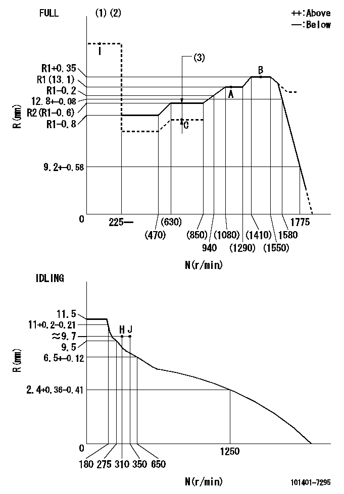
N:Pump speed
R:Rack position (mm)
(1)Torque cam stamping: T1
(2)Tolerance for racks not indicated: +-0.05mm.
(3)Boost compensator stroke: BCL
----------
T1=K06 BCL=0.45+-0.1mm
----------
----------
T1=K06 BCL=0.45+-0.1mm
----------
Speed control lever angle
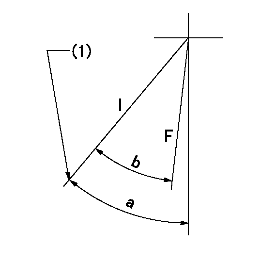
F:Full speed
I:Idle
(1)Stopper bolt set position 'H' (rack position = aa, speed = bb)
----------
aa=(9.7)mm bb=310r/min
----------
a=40deg+-5deg b=(39deg)+-3deg
----------
aa=(9.7)mm bb=310r/min
----------
a=40deg+-5deg b=(39deg)+-3deg
Stop lever angle
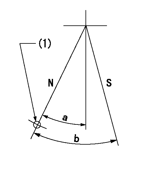
N:Pump normal
S:Stop the pump.
(1)Use the hole at R = aa
----------
aa=64mm
----------
a=20deg+-5deg b=29deg+-5deg
----------
aa=64mm
----------
a=20deg+-5deg b=29deg+-5deg
0000001501 FICD
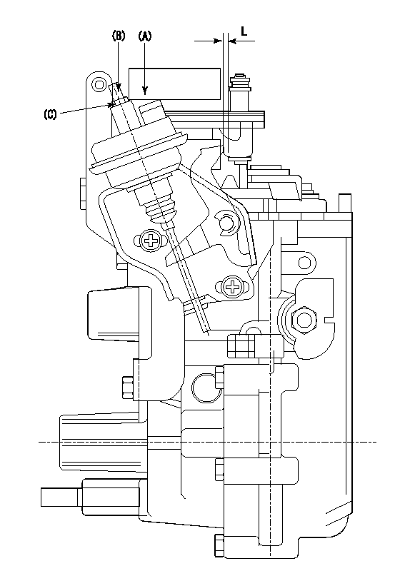
(A) applied negative pressure
(B) Screw
(c) Nut
1. Set the actuator as described below.
(1)Confirm that there is clearance between the actuator lever and the speed lever.
(2)Loosen the nut (C).
(3)Push in the screw (B).
(4)Apply P1 from the actuator (A) part.
(5)Pull out the screw (B) slowly.
(6)Tighten and fix the nut (C) when pump speed is Na and the rack position is Ra.
(7)Torque the nut (C) to T1.
(8)Apply P2 several times.
(9)Confirm that the actuator functions normally.
(10)Confirm that there is a clearance between the actuator lever and the speed lever at that time.
----------
P1=53.3kPa(400mmHg) P2=53.3kPa(400mmHg) Na=425r/min Ra=9.1+-0.1mm T1=1.2~1.6N-m(0.12~0.16kgf-m)
----------
L=(5)mm
----------
P1=53.3kPa(400mmHg) P2=53.3kPa(400mmHg) Na=425r/min Ra=9.1+-0.1mm T1=1.2~1.6N-m(0.12~0.16kgf-m)
----------
L=(5)mm
Timing setting
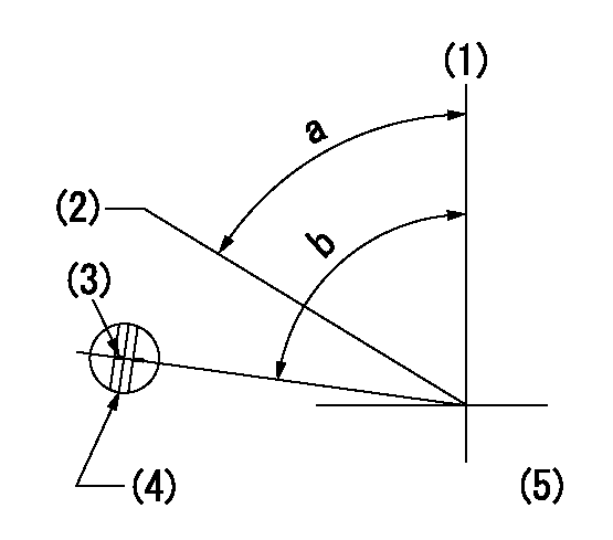
(1)Pump vertical direction
(2)Position of gear's standard threaded hole at No 1 cylinder's beginning of injection
(3)Stamping position on the A/T outer rim
(4)At the No 1 cylinder's beginning of injection, align with the aligning mark seen through the bracket's check hole and mark the A/T's bevel C1.
(5)B.T.D.C.: aa
----------
aa=7deg
----------
a=(60deg) b=(85deg)
----------
aa=7deg
----------
a=(60deg) b=(85deg)
Information:
Lubrication System
OIL LUBRICATION SCHEMATICThe lubrication system is the pressure type. The oil pump draws oil from the sump through a suction pipe and strainer to the pump. The oil pump is driven by the auxiliary drive group which is driven by the timing gears.Pressure oil flows to the oil cooler. The oil cooler is cooled by water from the cooling system. Coolers on T6.3544 Engines have a bypass valve that allows the oil to go around the cooler in case of a restriction or if the oil is too cold and thick. From the cooler, oil passes through the relief valve. On T6.3544 Engines, the relief valve is two stage. At 205 to 225 kPa (30 to 37 psi), oil is fed by a pipe to the piston cooling jet gallery which is a drilled passage the length of the crankcase, above the camshaft chamber. The piston cooling jets are bolted into the gallery and point into the bottom of each cylinder. Oil is sprayed onto the underneath side of each piston which takes heat from the combustion area. The oil then drains back to sump.At 345 to 415 kPa (50 to 60 psi), oil passes through a single oil filter on 6.3544 Engines or two filters on T6.3544 Engines. Oil then flows to the main oil gallery which is a drilled passage the length of the crankcase. Oil also flows from the filters to the turbocharger bearings on T6.3544 Engines. Passages in the crankcase webs feed oil from the main oil gallery to the main bearings. Passages in the crankshaft carry oil to the big end bearings. Through passages in No. 1, 3, 5 and 7 crankcase webs, oil passes from the main bearings to lubricate the camshaft bearings.The No. 2 camshaft bearing supplies a controlled amount of oil to the rocker shaft assembly, which then flows through a small bleed hole in each rocker lever to lubricate the valves and springs.Pistons, cylinder liners, connecting rod small end bushings, cam lobes and valve lifters are splash and oil mist lubricated.Oil flows from the main oil gallery to the two idler gear hubs. The oil passes through the hubs to radial passages in the idler gears to lubricate the teeth of the timing gears.The auxiliary drive group shaft bearings are lubricated by a passage from the main oil gallery to the front auxiliary drive shaft bearing. Oil then passes around a groove in the bearing journal and through another passage along the outer side of the auxiliary drive housing to the rear auxiliary drive shaft bearing. The upper fuel pump bearing is also lubricated from this passage. Also connected to this outer housing passage is a spray tube which directs oil on to the auxiliary drive shaft (worn gear) and gear assembly (worm wheel).Air Inlet And Exhaust System
6.3544 Engines
AIR INLET AND EXHAUST SYSTEM COMPONENTS
1. Exhaust manifold. 2. Inlet manifold. 3. Engine cylinderThe air inlet and exhaust system components on naturally aspirated engines are: the air cleaner, inlet manifold,
Have questions with 101401-7295?
Group cross 101401-7295 ZEXEL
Isuzu
Nissan
Isuzu
Nissan
Isuzu
101401-7295
9 400 613 750
8971467781
INJECTION-PUMP ASSEMBLY
4HE1-T
4HE1-T
