Information injection-pump assembly
BOSCH
F 01G 09U 00X
f01g09u00x
ZEXEL
101401-7293
1014017293
Rating:
Service parts 101401-7293 INJECTION-PUMP ASSEMBLY:
1.
_
6.
COUPLING PLATE
7.
COUPLING PLATE
8.
_
9.
_
11.
Nozzle and Holder
8-97115-503-1
12.
Open Pre:MPa(Kqf/cm2)
17.7{180}/21.6{220}
14.
NOZZLE
Cross reference number
BOSCH
F 01G 09U 00X
f01g09u00x
ZEXEL
101401-7293
1014017293
Zexel num
Bosch num
Firm num
Name
Calibration Data:
Adjustment conditions
Test oil
1404 Test oil ISO4113 or {SAEJ967d}
1404 Test oil ISO4113 or {SAEJ967d}
Test oil temperature
degC
40
40
45
Nozzle and nozzle holder
105780-8250
Bosch type code
1 688 901 101
Nozzle
105780-0120
Bosch type code
1 688 901 990
Nozzle holder
105780-2190
Opening pressure
MPa
20.7
Opening pressure
kgf/cm2
211
Injection pipe
Outer diameter - inner diameter - length (mm) mm 6-2-600
Outer diameter - inner diameter - length (mm) mm 6-2-600
Overflow valve
134424-3920
Overflow valve opening pressure
kPa
127
107
147
Overflow valve opening pressure
kgf/cm2
1.3
1.1
1.5
Tester oil delivery pressure
kPa
255
255
255
Tester oil delivery pressure
kgf/cm2
2.6
2.6
2.6
Direction of rotation (viewed from drive side)
Left L
Left L
Injection timing adjustment
Direction of rotation (viewed from drive side)
Left L
Left L
Injection order
1-3-4-2
Pre-stroke
mm
3.8
3.75
3.85
Rack position
Point A R=A
Point A R=A
Beginning of injection position
Governor side NO.1
Governor side NO.1
Difference between angles 1
Cal 1-3 deg. 90 89.5 90.5
Cal 1-3 deg. 90 89.5 90.5
Difference between angles 2
Cal 1-4 deg. 180 179.5 180.5
Cal 1-4 deg. 180 179.5 180.5
Difference between angles 3
Cyl.1-2 deg. 270 269.5 270.5
Cyl.1-2 deg. 270 269.5 270.5
Injection quantity adjustment
Adjusting point
-
Rack position
13.1
Pump speed
r/min
1160
1160
1160
Average injection quantity
mm3/st.
97
95.4
98.6
Max. variation between cylinders
%
0
-4
4
Basic
*
Fixing the rack
*
Standard for adjustment of the maximum variation between cylinders
*
Injection quantity adjustment_02
Adjusting point
Z
Rack position
9.7+-0.5
Pump speed
r/min
285
285
285
Average injection quantity
mm3/st.
14.5
13.2
15.8
Max. variation between cylinders
%
0
-14
14
Fixing the rack
*
Standard for adjustment of the maximum variation between cylinders
*
Injection quantity adjustment_03
Adjusting point
A
Rack position
R1(13.1)
Pump speed
r/min
1160
1160
1160
Average injection quantity
mm3/st.
97
96
98
Basic
*
Fixing the lever
*
Boost pressure
kPa
60
60
Boost pressure
mmHg
450
450
Injection quantity adjustment_04
Adjusting point
B
Rack position
R1+0.35
Pump speed
r/min
1450
1450
1450
Average injection quantity
mm3/st.
96.5
92.5
100.5
Fixing the lever
*
Boost pressure
kPa
60
60
Boost pressure
mmHg
450
450
Injection quantity adjustment_05
Adjusting point
C
Rack position
R2-0.45
Pump speed
r/min
700
700
700
Average injection quantity
mm3/st.
86
82
90
Fixing the lever
*
Boost pressure
kPa
0
0
0
Boost pressure
mmHg
0
0
0
Injection quantity adjustment_06
Adjusting point
I
Rack position
-
Pump speed
r/min
150
150
150
Average injection quantity
mm3/st.
95
95
127
Fixing the lever
*
Boost pressure
kPa
0
0
0
Boost pressure
mmHg
0
0
0
Boost compensator adjustment
Pump speed
r/min
700
700
700
Rack position
R2-0.45
Boost pressure
kPa
27.3
26
28.6
Boost pressure
mmHg
205
195
215
Boost compensator adjustment_02
Pump speed
r/min
700
700
700
Rack position
R2(R1-0.
6)
Boost pressure
kPa
46.7
46.7
46.7
Boost pressure
mmHg
350
350
350
Timer adjustment
Pump speed
r/min
1185--
Advance angle
deg.
0
0
0
Remarks
Start
Start
Timer adjustment_02
Pump speed
r/min
1135
Advance angle
deg.
0.5
Timer adjustment_03
Pump speed
r/min
1450
Advance angle
deg.
4.8
4.3
5.3
Timer adjustment_04
Pump speed
r/min
-
Advance angle
deg.
5
4.5
5.5
Remarks
Measure the actual speed, stop
Measure the actual speed, stop
Test data Ex:
Governor adjustment
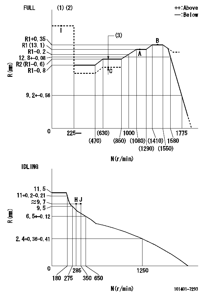
N:Pump speed
R:Rack position (mm)
(1)Torque cam stamping: T1
(2)Tolerance for racks not indicated: +-0.05mm.
(3)Boost compensator stroke: BCL
----------
T1=K06 BCL=0.45+-0.1mm
----------
----------
T1=K06 BCL=0.45+-0.1mm
----------
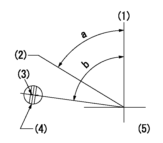
Speed control lever angle
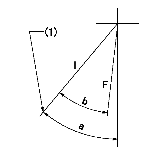
F:Full speed
I:Idle
(1)Stopper bolt set position 'H'
----------
----------
a=42deg+-5deg b=(41deg)+-3deg
----------
----------
a=42deg+-5deg b=(41deg)+-3deg
Stop lever angle
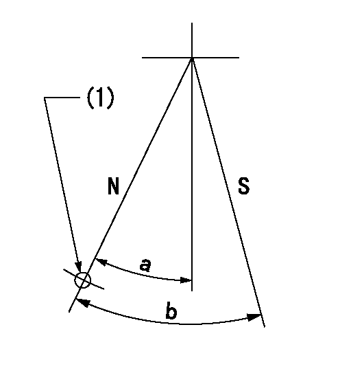
N:Pump normal
S:Stop the pump.
(1)Use the hole at R = aa
----------
aa=64mm
----------
a=20deg+-5deg b=29deg+-5deg
----------
aa=64mm
----------
a=20deg+-5deg b=29deg+-5deg
0000001501 FICD
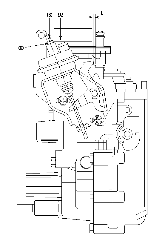
(A) applied negative pressure
(B) Screw
(c) Nut
1. Set the actuator as described below.
(1)Confirm that there is clearance between the actuator lever and the speed lever.
(2)Loosen the nut (C).
(3)Push in the screw (B).
(4)Apply P1 from the actuator (A) part.
(5)Pull out the screw (B) slowly.
(6)Tighten and fix the nut (C) when pump speed is Na and the rack position is Ra.
(7)Torque the nut (C) to T1.
(8)Apply P2 several times.
(9)Confirm that the actuator functions normally.
(10)Confirm that there is a clearance between the actuator lever and the speed lever at that time.
----------
P1=53.3kPa(400mmHg) P2=53.3kPa(400mmHg) Na=410r/min Ra=9.75+-0.1mm T1=1.2~1.6N-m(0.12~0.16kgf-m)
----------
L=(5)mm
----------
P1=53.3kPa(400mmHg) P2=53.3kPa(400mmHg) Na=410r/min Ra=9.75+-0.1mm T1=1.2~1.6N-m(0.12~0.16kgf-m)
----------
L=(5)mm
Timing setting
(1)Pump vertical direction
(2)Position of gear's standard threaded hole at No 1 cylinder's beginning of injection
(3)Stamping position on the A/T outer rim
(4)At the No 1 cylinder's beginning of injection, align with the aligning mark seen through the bracket's check hole and mark the A/T's bevel C1.
(5)B.T.D.C.: aa
----------
aa=7deg
----------
a=(60deg) b=(85deg)
----------
aa=7deg
----------
a=(60deg) b=(85deg)
Information:
Lubrication System
Oil Lubrication Schematic
Oil Pump
(1) Strainer. (2) Oil Pump relief valve. (3) Oil pump. (4) Idler gear. (5) Crankshaft gear.The lubrication system is the pressure type and the flow of oil goes from the oil pan through strainer (1) into oil pump (3). Oil pump (3) is driven by crankshaft gear (5) through idler gear (4). The oil pump is connected to the front main bearing cap. Relief valve (2) which is spring loaded controls the maximum oil pressure. An oil pressure sending unit is connected to the main oil gallery.Oil under pressure goes from the oil pump through the relief valve and filter. On the T4.236 Engines, oil passes first through the oil cooler. The oil cooler is cooled by water from the cooling system. On engines that have a center mounted balancer unit, the oil pump and relief valve are integral with the balancer unit.Oil flows through the filter to the main oil gallery which is a drilled passage the length of the crankcase. A pipe from the filter head feeds oil to the turbocharger bearings on T4.236 Engines.From the gallery the oil flows through drilled passages to the main bearing bores and then through the crankshaft passages to the big end (rod) bearings. T4.236 Engine oil also flows from the main oil gallery to the piston cooling jets which have integral relief valves. The piston cooling jets feed oil to the underside of the pistons, where the oil circulates, taking heat from the combustion area. The cooling jets start operation at approximately 205 kPa (30 psi).
Timing Gears
(6) Idler gear. (7) Idler gear retainer plate.The crankshaft bearings are lubricated from numbers 1, 3 and 5 main bearings. The camshaft center bearing supplies a controlled amount of oil to the rocker shaft assembly. Oil from the rocker shaft drains through a bleed hole in each rocker lever to lubricate the valves and valve guides.Oil also goes from the gallery through the rear of idler gear (6) hub, then through passages to lubricate the idler gear bearing and gear retainer plate (7).Pistons, cylinder liners, connecting rod small end bushings, cam lobes and tappets (valve lifters) are splash and oil mist lubricated.Balancer Unit
Center Mounted Balancer Unit Components
(1) Idler gear hub. (2) Idler gear bearing. (3) Idler gear. (4) Idler gear thrust washer. (5) Balance weight bushings. (6) Balance weights. (7) Oil transfer cover plate. (8) Balancer frame. (9) Oil pump relief valve assembly. (10) Balance weights drive gear. (11) Gear shaft drive bearings. (12) Gear shaft drive. (13) Oil pump. (14) Oil suction pipe.Engines that are mounted stationary (rigid) have a balancer unit that is mounted to the block bottom face in the center of the engine. The balancer unit is timed to and driven by the crankshaft through a gear on the crankshaft and idler gear (3). The rotation of timed balance weights (10) counteracts the movement of the pistons and connecting rods of the engine.Oil pump (13) is part of and is driven by the balancer unit