Information injection-pump assembly
BOSCH
9 400 613 744
9400613744
ZEXEL
101401-7225
1014017225
ISUZU
8971467751
8971467751
Rating:
Service parts 101401-7225 INJECTION-PUMP ASSEMBLY:
1.
_
6.
COUPLING PLATE
7.
COUPLING PLATE
8.
_
9.
_
11.
Nozzle and Holder
12.
Open Pre:MPa(Kqf/cm2)
18.1(185)

15.
NOZZLE SET
Cross reference number
BOSCH
9 400 613 744
9400613744
ZEXEL
101401-7225
1014017225
ISUZU
8971467751
8971467751
Zexel num
Bosch num
Firm num
Name
101401-7225
9 400 613 744
8971467751 ISUZU
INJECTION-PUMP ASSEMBLY
4HG1 K 14BD INJECTION PUMP ASSY PE4AD PE
4HG1 K 14BD INJECTION PUMP ASSY PE4AD PE
Calibration Data:
Adjustment conditions
Test oil
1404 Test oil ISO4113 or {SAEJ967d}
1404 Test oil ISO4113 or {SAEJ967d}
Test oil temperature
degC
40
40
45
Nozzle and nozzle holder
105780-8140
Bosch type code
EF8511/9A
Nozzle
105780-0000
Bosch type code
DN12SD12T
Nozzle holder
105780-2080
Bosch type code
EF8511/9
Opening pressure
MPa
17.2
Opening pressure
kgf/cm2
175
Injection pipe
Outer diameter - inner diameter - length (mm) mm 6-2-600
Outer diameter - inner diameter - length (mm) mm 6-2-600
Overflow valve
134424-3920
Overflow valve opening pressure
kPa
127
107
147
Overflow valve opening pressure
kgf/cm2
1.3
1.1
1.5
Tester oil delivery pressure
kPa
157
157
157
Tester oil delivery pressure
kgf/cm2
1.6
1.6
1.6
Direction of rotation (viewed from drive side)
Left L
Left L
Injection timing adjustment
Direction of rotation (viewed from drive side)
Left L
Left L
Injection order
1-3-4-2
Pre-stroke
mm
4.1
4.05
4.15
Rack position
Point B R=B
Point B R=B
Beginning of injection position
Governor side NO.1
Governor side NO.1
Difference between angles 1
Cal 1-3 deg. 90 89.5 90.5
Cal 1-3 deg. 90 89.5 90.5
Difference between angles 2
Cal 1-4 deg. 180 179.5 180.5
Cal 1-4 deg. 180 179.5 180.5
Difference between angles 3
Cyl.1-2 deg. 270 269.5 270.5
Cyl.1-2 deg. 270 269.5 270.5
Injection quantity adjustment
Adjusting point
-
Rack position
11.9
Pump speed
r/min
1600
1600
1600
Average injection quantity
mm3/st.
92.5
90.9
94.1
Max. variation between cylinders
%
0
-4
4
Basic
*
Fixing the rack
*
Standard for adjustment of the maximum variation between cylinders
*
Injection quantity adjustment_02
Adjusting point
H'
Rack position
9.4+-0.5
Pump speed
r/min
310
310
310
Average injection quantity
mm3/st.
11
9.7
12.3
Max. variation between cylinders
%
0
-10
10
Fixing the rack
*
Standard for adjustment of the maximum variation between cylinders
*
Injection quantity adjustment_03
Adjusting point
H
Rack position
9.4+-0.5
Pump speed
r/min
325
325
325
Average injection quantity
mm3/st.
10.5
9.2
11.8
Fixing the rack
*
Injection quantity adjustment_04
Adjusting point
A
Rack position
R1(11.9)
Pump speed
r/min
1600
1600
1600
Average injection quantity
mm3/st.
92.5
91.5
93.5
Basic
*
Fixing the lever
*
Injection quantity adjustment_05
Adjusting point
B
Rack position
R1-0.5
Pump speed
r/min
960
960
960
Average injection quantity
mm3/st.
74.5
70.5
78.5
Fixing the lever
*
Timer adjustment
Pump speed
r/min
1150--
Advance angle
deg.
0
0
0
Remarks
Start
Start
Timer adjustment_02
Pump speed
r/min
1100
Advance angle
deg.
0.5
Timer adjustment_03
Pump speed
r/min
1600
Advance angle
deg.
6
5.5
6.5
Remarks
Finish
Finish
Test data Ex:
Governor adjustment
N:Pump speed
R:Rack position (mm)
(1)Torque cam stamping: T1
(2)Tolerance for racks not indicated: +-0.05mm.
----------
T1=K90
----------
----------
T1=K90
----------
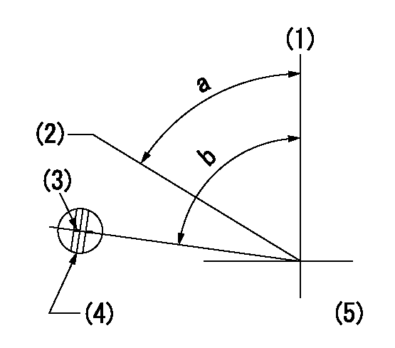
Speed control lever angle
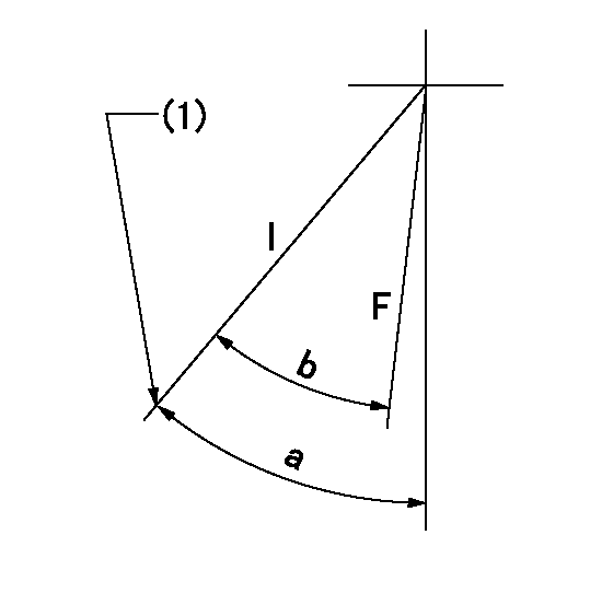
F:Full speed
I:Idle
(1)Stopper bolt set position 'H' (rack position = aa, speed = bb)
----------
aa=(9.4)mm bb=325r/min
----------
a=41.5deg+-5deg b=40.5deg+-3deg
----------
aa=(9.4)mm bb=325r/min
----------
a=41.5deg+-5deg b=40.5deg+-3deg
Stop lever angle
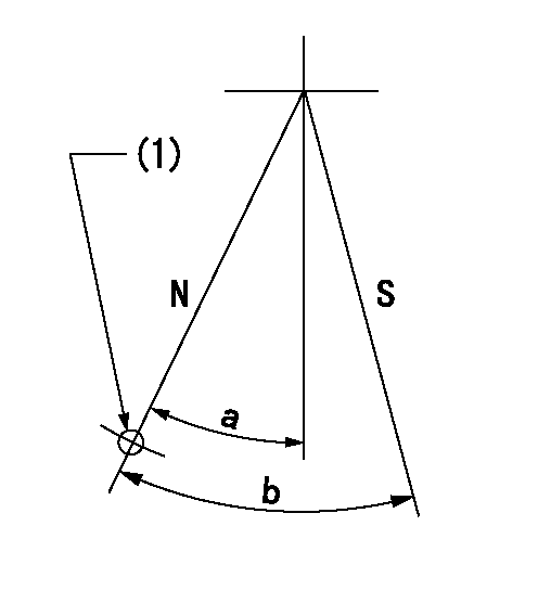
N:Pump normal
S:Stop the pump.
(1)Use the hole at R = aa
----------
aa=64mm
----------
a=20deg+-5deg b=29deg+-5deg
----------
aa=64mm
----------
a=20deg+-5deg b=29deg+-5deg
0000001501 FICD
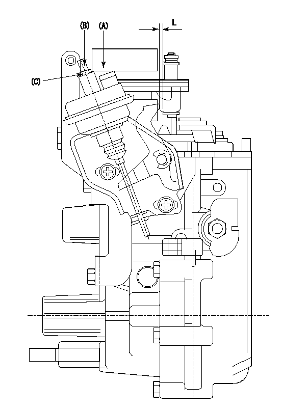
(A) applied negative pressure
(B) Screw
(c) Nut
1. Set the actuator as described below.
(1)Confirm that there is clearance between the actuator lever and the speed lever.
(2)Loosen the nut (C).
(3)Push in the screw (B).
(4)Apply P1 from the actuator (A) part.
(5)Pull out the screw (B) slowly.
(6)Tighten and fix the nut (C) when pump speed is Na and the rack position is Ra.
(7)Torque the nut (C) to T1.
(8)Apply P2 several times.
(9)Confirm that the actuator functions normally.
(10)Confirm that there is a clearance between the actuator lever and the speed lever at that time.
----------
P1=53.3kPa(400mmHg) P2=53.3kPa(400mmHg) Na=410r/min Ra=9.2+-0.1mm T1=1.2~1.6N-m(0.12~0.16kgf-m)
----------
L=(5)mm
----------
P1=53.3kPa(400mmHg) P2=53.3kPa(400mmHg) Na=410r/min Ra=9.2+-0.1mm T1=1.2~1.6N-m(0.12~0.16kgf-m)
----------
L=(5)mm
0000001601 RACK SENSOR
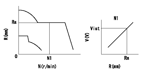
Rack sensor adjustment
1. Flange type rack sensor (rack sensor adjustment -5*20)
(1)These types of rack sensors do not need adjustment. Confirm the performance with the following procedures.
(2)Mount the rack sensor main body to the pump main body.
(3)Fix the pump lever at full.
(4)At supply voltage V1, pump speed N1 and rack position Ra, confirm that the amp's output voltage is Vist.
(5)Move the pump lever two or three times.
(6)Set again to full.
(7)Confirm that the amplifier output voltage is Vist.
(8)Fix the caution plate to the upper part of the rack sensor.
(For those without the caution plate instructions, make sure the nameplate of the rack sensor carries the "Don't hold here" caution.)
(9)Apply red paint to the rack sensor mounting bolts (2 places).
----------
V1=5+-0.01V N1=960r/min Ra=R1(11.9)-0.5mm Vist=2.44+-0.28V
----------
----------
V1=5+-0.01V N1=960r/min Ra=R1(11.9)-0.5mm Vist=2.44+-0.28V
----------
Timing setting
(1)Pump vertical direction
(2)Position of gear's standard threaded hole at No 1 cylinder's beginning of injection
(3)Timing device stamping
(4)At the No 1 cylinder's beginning of injection, align with the aligning mark seen through the bracket's check hole and mark the A/T's bevel C1.
(5)B.T.D.C.: aa
----------
aa=7deg
----------
a=(60deg) b=(85deg)
----------
aa=7deg
----------
a=(60deg) b=(85deg)
Information:
C. Put a small amount of lubricant, such as Lubriplate, on the nut seat area on the compressor. Do not put lubricant on the threads.D. Tighten the compressor wheel retainer nut to ... 30 3 N m (264 24 lb in)
Do not bend or add stress to the shaft when nut is tightened.
(7) Bore in housing (new) ... 22.255 to 22.268 mm (.8762 to .8767 in) Outside diameter of the bearing (new) ... 22.144 to 22.154 mm (.8718 to .8722 in)Maximum permissible clearance between bearing and bore in housing (worn) ... 0.15 mm (.006 in)(8) Thickness of each thrust ring ... 2.553 0.013 mm (.1005 .0005 in)(9) Put 5P3931 Anti-Seize Compound on threads and tighten bolts that hold turbocharger to manifold to ... 55 5 N m (40 4 lb ft)Schwitzer S4D
(1) End play for shaft (new) ... 0.114 0.038 mm (.0045 .0015 in) Maximum permissible end play (worn) ... 0.20 mm (.008 in)(2) Thickness of thrust bearing (where thrust rings contact bearing) ... 5.36 0.03 mm (.211 .001 in)(3) Bore in housing (new) ... 24.994 to 25.006 mm (.9840 to .9845 in) Outside diameter of the bearing (new) ... 24.882 to 24.892 mm (.9796 to .9800 in)Maximum permissible clearance between bearing and bore in housing (worn) ... 0.15 mm (.006 in)(4) Maximum permissible gap of oil seal ring, measured in bore of housing ... 0.25 mm (.010 in)(5) Install the compressor wheel (at room temperature) as follows: a. Put the compressor wheel in position on the shaft.b. Put a small amount of clean engine oil on the shaft threads.c. Install the nut on the shaft, and tighten the nut to a torque of 14 to 17 N m (125 to 150 lb in).
Do not bend or add stress to the shaft when nut is loosened or tightened.
d. Remove nut from shaft and apply 6V1541 Quick Cure Primer on the threads of the shaft and nut followed by application of 9S3265 Retaining Compound.e. Install the nut on the shaft, and tighten the nut to a torque of 4 N m (30 lb in).f. Tighten nut more as follows: For 99.0 mm (3.90 in) diameter compressor wheels, tighten the nut an additional 90°.For 86.4 mm (3.40 in) diameter compressor wheels, tighten the nut an additional 60°.(6) Tighten both band clamps with procedure that follows: a. Tighten to ... 14 1.1 N m (125 10 lb in)b. Tap (hit) clamp lightly all around.c. Tighten again to ... 14 1.1 N m (125 10 lb in)
Do not overtighten the clamps.
(7) Thickness of each thrust ring ... 2.553 0.013 mm (.1005 .0005 in)(8) Diameter of shaft (new) ... 15.997 to 16.005 mm (.6298 to .6301 in) Bore in the bearing (new) ... 16.035 to 16.043 mm (.6313 to .6316 in)Maximum permissible clearance between bearing and shaft (worn) ... 0.05 mm (.002 in)Torque for four nuts (put 5P3931 Anti-Seize Compound on threads) and bolts that hold the
Have questions with 101401-7225?
Group cross 101401-7225 ZEXEL
Isuzu
Nissan
Isuzu
Nissan
Isuzu
101401-7225
9 400 613 744
8971467751
INJECTION-PUMP ASSEMBLY
4HG1
4HG1