Information injection-pump assembly
BOSCH
F 01G 09U 008
f01g09u008
ZEXEL
101401-7091
1014017091
ISUZU
8971223590
8971223590

Rating:
Include in #1:
106671-8303
as _
Cross reference number
BOSCH
F 01G 09U 008
f01g09u008
ZEXEL
101401-7091
1014017091
ISUZU
8971223590
8971223590
Zexel num
Bosch num
Firm num
Name
101401-7091
F 01G 09U 008
8971223590 ISUZU
INJECTION-PUMP ASSEMBLY
4HF1 * K
4HF1 * K
Calibration Data:
Adjustment conditions
Test oil
1404 Test oil ISO4113 or {SAEJ967d}
1404 Test oil ISO4113 or {SAEJ967d}
Test oil temperature
degC
40
40
45
Nozzle and nozzle holder
105780-8140
Bosch type code
EF8511/9A
Nozzle
105780-0000
Bosch type code
DN12SD12T
Nozzle holder
105780-2080
Bosch type code
EF8511/9
Opening pressure
MPa
17.2
Opening pressure
kgf/cm2
175
Injection pipe
Outer diameter - inner diameter - length (mm) mm 6-2-600
Outer diameter - inner diameter - length (mm) mm 6-2-600
Overflow valve
131424-4920
Overflow valve opening pressure
kPa
127
107
147
Overflow valve opening pressure
kgf/cm2
1.3
1.1
1.5
Tester oil delivery pressure
kPa
157
157
157
Tester oil delivery pressure
kgf/cm2
1.6
1.6
1.6
Direction of rotation (viewed from drive side)
Left L
Left L
Injection timing adjustment
Direction of rotation (viewed from drive side)
Left L
Left L
Injection order
1-3-4-2
Pre-stroke
mm
4.1
4.05
4.15
Rack position
Point A R=A
Point A R=A
Beginning of injection position
Governor side NO.1
Governor side NO.1
Difference between angles 1
Cal 1-3 deg. 90 89.5 90.5
Cal 1-3 deg. 90 89.5 90.5
Difference between angles 2
Cal 1-4 deg. 180 179.5 180.5
Cal 1-4 deg. 180 179.5 180.5
Difference between angles 3
Cyl.1-2 deg. 270 269.5 270.5
Cyl.1-2 deg. 270 269.5 270.5
Injection quantity adjustment
Adjusting point
-
Rack position
12
Pump speed
r/min
960
960
960
Average injection quantity
mm3/st.
54
52.4
55.6
Max. variation between cylinders
%
0
-4
4
Basic
*
Fixing the rack
*
Standard for adjustment of the maximum variation between cylinders
*
Injection quantity adjustment_02
Adjusting point
H
Rack position
9.8+-0.5
Pump speed
r/min
285
285
285
Average injection quantity
mm3/st.
14
12.7
15.3
Max. variation between cylinders
%
0
-10
10
Fixing the rack
*
Standard for adjustment of the maximum variation between cylinders
*
Injection quantity adjustment_03
Adjusting point
A
Rack position
R1(12)
Pump speed
r/min
960
960
960
Average injection quantity
mm3/st.
54
53
55
Basic
*
Fixing the lever
*
Injection quantity adjustment_04
Adjusting point
B
Rack position
R1+0.1
Pump speed
r/min
1600
1600
1600
Average injection quantity
mm3/st.
65
61
69
Fixing the lever
*
Injection quantity adjustment_05
Adjusting point
C
Rack position
R1-0.2
Pump speed
r/min
500
500
500
Average injection quantity
mm3/st.
46.5
42.5
50.5
Fixing the lever
*
Timer adjustment
Pump speed
r/min
1050--
Advance angle
deg.
0
0
0
Remarks
Start
Start
Timer adjustment_02
Pump speed
r/min
1000
Advance angle
deg.
0.5
Timer adjustment_03
Pump speed
r/min
1600
Advance angle
deg.
5
4.5
5.5
Remarks
Finish
Finish
Test data Ex:
Governor adjustment
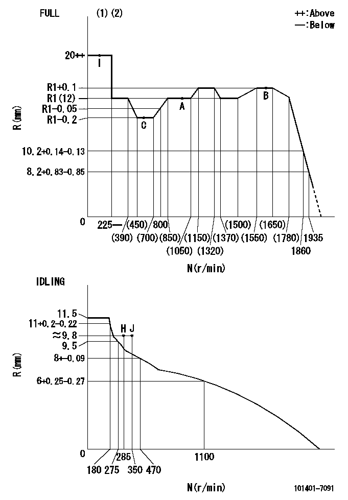
N:Pump speed
R:Rack position (mm)
(1)Torque cam stamping: T1
(2)Tolerance for racks not indicated: +-0.05mm.
----------
T1=L48
----------
----------
T1=L48
----------
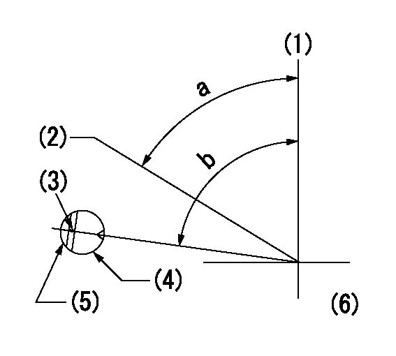
Speed control lever angle
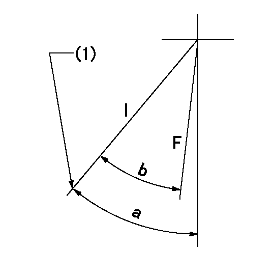
F:Full speed
I:Idle
(1)Stopper bolt set position 'H'
----------
----------
a=41deg+-5deg b=(35deg)+-3deg
----------
----------
a=41deg+-5deg b=(35deg)+-3deg
Stop lever angle
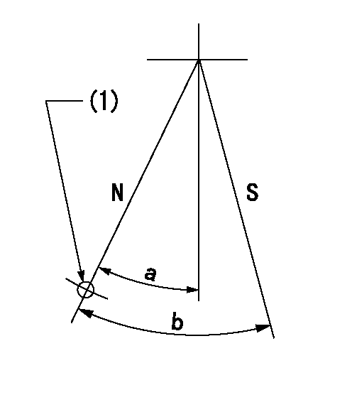
N:Pump normal
S:Stop the pump.
(1)Use the hole at R = aa
----------
aa=64mm
----------
a=20deg+-5deg b=29deg+-5deg
----------
aa=64mm
----------
a=20deg+-5deg b=29deg+-5deg
0000001501 ACS
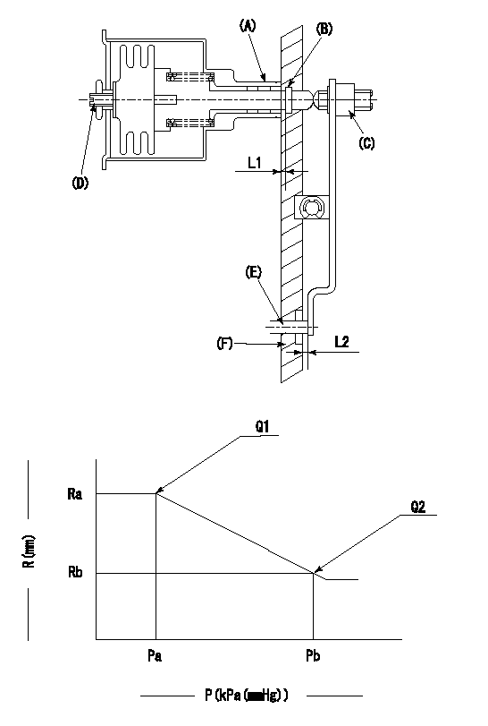
(A) Housing
(B) Snap ring
(C) adjusting screw
(D) Set screw
(E): Push rod
(F) Spacer
1. Adjustment of the aneroid compensator
(1)Adjust with the (D) set screw so that the clearance between the (A) housing and (B) snap ring is L1.
(2)Select the push rod (E) so that the distance from the end surface of the (F) spacer becomes L2.
(3)(C) Turn the screw to adjust the beginning of aneroid compensator operation.
2. Adjustment when mounting the governor.
(1)Set the speed of the pump to N1 r/min and fix the control lever at the full set position.
(2)Adjust using screw C to obtain the performance shown in the graph above.
(3)After final adjustment, confirm that the gap between housing (A) and snapring (B) is L3.
----------
N1=960r/min L1=1.4~1.7mm L2=0.5+-0.5mm L3=(0.1~0.5)mm
----------
Ra=R1(12)mm Rb=R1-0.4mm Pa=95.4+-5.3kPa(716+-40mmHg) Pb=70.1+-0.7kPa(526+-5mmHg) Q1=54+-1cm3/1000st Q2=(40)+-1.6cm3/1000st
----------
N1=960r/min L1=1.4~1.7mm L2=0.5+-0.5mm L3=(0.1~0.5)mm
----------
Ra=R1(12)mm Rb=R1-0.4mm Pa=95.4+-5.3kPa(716+-40mmHg) Pb=70.1+-0.7kPa(526+-5mmHg) Q1=54+-1cm3/1000st Q2=(40)+-1.6cm3/1000st
Timing setting
(1)Pump vertical direction
(2)Position of gear's standard threaded hole at No 1 cylinder's beginning of injection
(3)Stamping position on the A/T outer rim
(4)Pump bracket check hole position.
(5)At the No 1 cylinder's beginning of injection, align with the projection seen through the bracket's check hole and mark the A/T's bevel C1.
(6)B.T.D.C.: aa
----------
aa=8deg
----------
a=(60deg) b=(85deg)
----------
aa=8deg
----------
a=(60deg) b=(85deg)
Information:
Use of the Pickup During Wet Conditions
If the pickup becomes wet, it may operate intermittently or not at all. Although the pickup is water resistant, it is not waterproof. Water spray from rain or other sources may cause the pickup to stop producing an output signal.If this happens, the pickup should be removed from the engine and allowed to dry out thoroughly. If necessary, the pickup can be dried in an oven at approximately 50°C (122°F). After drying, the pickup should operate correctly.If it is not possible to keep the pickup dry, use the following procedure: If the pickup must be used during wet conditions, it may be possible to protect it from moisture by using a water displacing spray such as WD-40®.Remove the pickup from the engine. Thoroughly spray the pickup from all directions. Make sure the pickup is completely covered with the spray. Reinstall the pickup on the engine and check its operation.When water first contacts the pickup, the unit may stop working temporarily, but will start working again after the water has been displaced by the solution. If necessary, spray the solution on the pickup after installation on the injection line.Permanent Installation on the Engine
If the pickup is to be permanently installed on the engine, install the pickup on the fuel injection line in the usual manner. Make sure that the thumbscrew is hand tightened securely, but not over tightened. Run the engine and check the operation of the pickup.Make sure that the pickup and line are clean and dry. If the pickup is working correctly, use a can of spray paint to thoroughly paint the pickup from all directions. Several coats should be applied. Let the paint dry thoroughly before operating the engine.Checking the Operation of the Amplifier and Pickup
(1) 6V2100 Multitach. (2) 5P9698 Calibrator. (3) 5P7366 Power Cable. (4) Digital Multimeter. (5) Screwdriver. (6) 6V6152 Adapter. Screwdriver (5) should have a blade approximately 150 mm (6 in) long with 6 mm (.25 in) diameter shaft of round bare metal (not anodized or insulated).The 6V6152 Adapter (6) is a phono plug-to-BNC connector. Modifications must be made to the 5P9698 Calibrator (2). Refer to Special Instruction, SMHS7504-01.Checking the 4C6812 Amplifier
(1) 6V6152 Adapter Plug. (2) 5P9698 Calibrator. (3) 4C6812 Amplifier. (4) Connector. (5) 5P7366 Power Cable. (6) Knob. (7) Battery Indicator. (8) No Input Signal Light.1. Install 6V6152 Adapter Plug (1) on the end of the output cable on 5P9698 Calibrator (2). Plug the adapter into 4C6812 Amplifier (3).2. Check the operation of the multitach being used by performing the CHECKING PHOTO OPERATION test procedure contained in Special Instruction SEHS7807. (This is to ensure it is operating correctly on PHOTO operation.)3. Plug connector (4), on the end of the amplifier output cable, into the PH (photo) connector on the multitach. Attach 5P7366 Power Cable (5) to the multitach and to a suitable power source. Refer to SEHS7807.4. Program the multitach for .5 P/REV and to read R/MIN on the PH (photo) input. Turn knob (6) on
Have questions with 101401-7091?
Group cross 101401-7091 ZEXEL
Isuzu
Isuzu
Nissan
Isuzu
Isuzu
Isuzu
Isuzu
101401-7091
F 01G 09U 008
8971223590
INJECTION-PUMP ASSEMBLY
4HF1
4HF1