Information injection-pump assembly
ZEXEL
101401-7050
1014017050

Rating:
Service parts 101401-7050 INJECTION-PUMP ASSEMBLY:
1.
_
6.
COUPLING PLATE
7.
COUPLING PLATE
8.
_
9.
_
11.
Nozzle and Holder
8-97119-811-0
12.
Open Pre:MPa(Kqf/cm2)
18.1{185}

15.
NOZZLE SET
Cross reference number
ZEXEL
101401-7050
1014017050
Zexel num
Bosch num
Firm num
Name
101401-7050
INJECTION-PUMP ASSEMBLY
14BD PE4AD PE
14BD PE4AD PE
Calibration Data:
Adjustment conditions
Test oil
1404 Test oil ISO4113 or {SAEJ967d}
1404 Test oil ISO4113 or {SAEJ967d}
Test oil temperature
degC
40
40
45
Nozzle and nozzle holder
105780-8140
Bosch type code
EF8511/9A
Nozzle
105780-0000
Bosch type code
DN12SD12T
Nozzle holder
105780-2080
Bosch type code
EF8511/9
Opening pressure
MPa
17.2
Opening pressure
kgf/cm2
175
Injection pipe
Outer diameter - inner diameter - length (mm) mm 6-2-600
Outer diameter - inner diameter - length (mm) mm 6-2-600
Overflow valve
134424-3920
Overflow valve opening pressure
kPa
127
107
147
Overflow valve opening pressure
kgf/cm2
1.3
1.1
1.5
Tester oil delivery pressure
kPa
157
157
157
Tester oil delivery pressure
kgf/cm2
1.6
1.6
1.6
Direction of rotation (viewed from drive side)
Left L
Left L
Injection timing adjustment
Direction of rotation (viewed from drive side)
Left L
Left L
Injection order
1-3-4-2
Pre-stroke
mm
4.1
4.05
4.15
Rack position
Point A R=A
Point A R=A
Beginning of injection position
Governor side NO.1
Governor side NO.1
Difference between angles 1
Cal 1-3 deg. 90 89.5 90.5
Cal 1-3 deg. 90 89.5 90.5
Difference between angles 2
Cal 1-4 deg. 180 179.5 180.5
Cal 1-4 deg. 180 179.5 180.5
Difference between angles 3
Cyl.1-2 deg. 270 269.5 270.5
Cyl.1-2 deg. 270 269.5 270.5
Injection quantity adjustment
Adjusting point
-
Rack position
12.2
Pump speed
r/min
960
960
960
Average injection quantity
mm3/st.
68
66.4
69.6
Max. variation between cylinders
%
0
-4
4
Basic
*
Fixing the rack
*
Standard for adjustment of the maximum variation between cylinders
*
Injection quantity adjustment_02
Adjusting point
H
Rack position
9.8+-0.5
Pump speed
r/min
285
285
285
Average injection quantity
mm3/st.
10
8.7
11.3
Max. variation between cylinders
%
0
-10
10
Fixing the rack
*
Standard for adjustment of the maximum variation between cylinders
*
Injection quantity adjustment_03
Adjusting point
A
Rack position
R1(12.2)
Pump speed
r/min
960
960
960
Average injection quantity
mm3/st.
68
67
69
Basic
*
Fixing the lever
*
Injection quantity adjustment_04
Adjusting point
B
Rack position
R1+0.45
Pump speed
r/min
1600
1600
1600
Average injection quantity
mm3/st.
87.5
83.5
91.5
Fixing the lever
*
Injection quantity adjustment_05
Adjusting point
C
Rack position
R1-0.15
Pump speed
r/min
520
520
520
Average injection quantity
mm3/st.
49.7
45.7
53.7
Fixing the lever
*
Injection quantity adjustment_06
Adjusting point
D
Rack position
R1+0.25
Pump speed
r/min
1310
1310
1310
Average injection quantity
mm3/st.
80
76
84
Fixing the lever
*
Timer adjustment
Pump speed
r/min
1150--
Advance angle
deg.
0
0
0
Remarks
Start
Start
Timer adjustment_02
Pump speed
r/min
1100
Advance angle
deg.
0.5
Timer adjustment_03
Pump speed
r/min
1600
Advance angle
deg.
6
5.5
6.5
Remarks
Finish
Finish
Test data Ex:
Governor adjustment
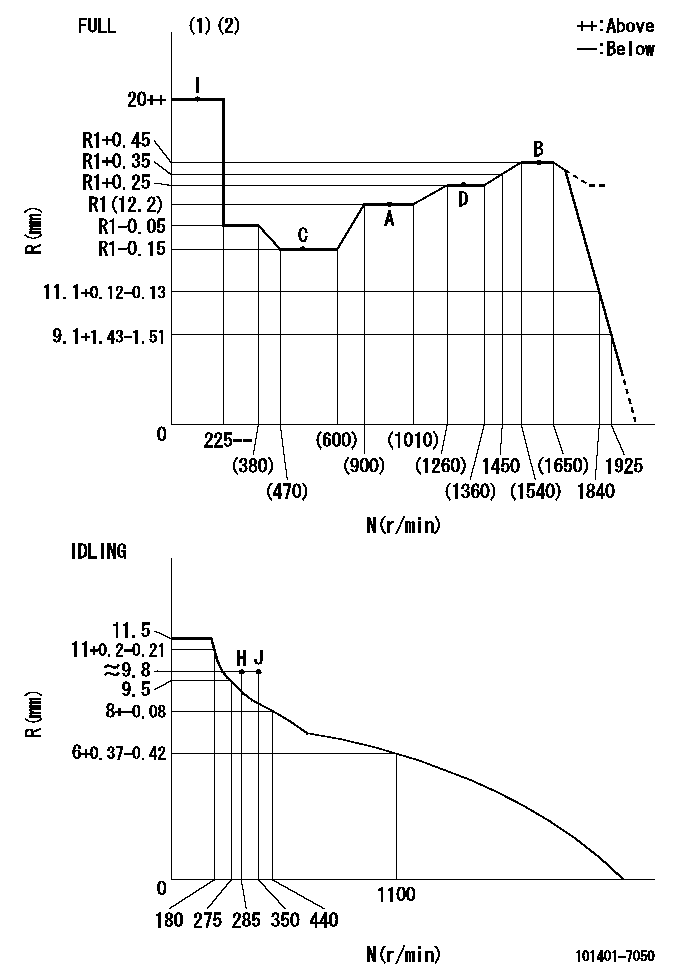
N:Pump speed
R:Rack position (mm)
(1)Torque cam stamping: T1
(2)Tolerance for racks not indicated: +-0.05mm.
----------
T1=J79
----------
----------
T1=J79
----------
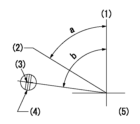
Speed control lever angle
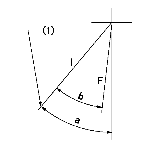
F:Full speed
I:Idle
(1)Stopper bolt set position 'H'
----------
----------
a=41deg+-5deg b=36deg+-3deg
----------
----------
a=41deg+-5deg b=36deg+-3deg
Stop lever angle
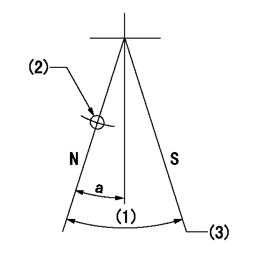
N:Pump normal
S:Stop the pump.
(1)(Actual measurement)
(2)Use the hole at R = aa
(3)At pump speed bb and rack position cc, set the stopper bolt.
----------
aa=25mm bb=1600r/min cc=5-0.5mm
----------
a=15deg+-5deg
----------
aa=25mm bb=1600r/min cc=5-0.5mm
----------
a=15deg+-5deg
0000001501 FICD
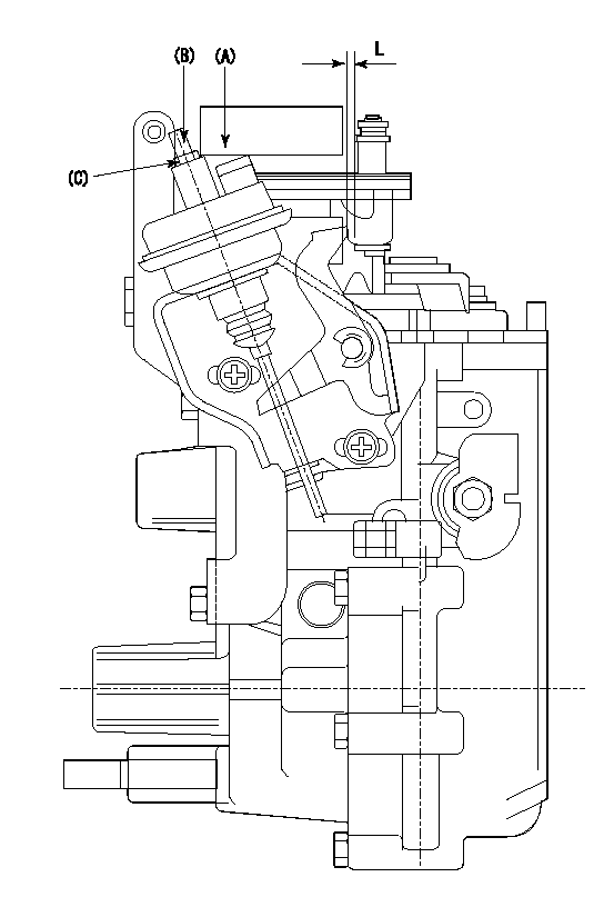
(A) applied negative pressure
(B) Screw
(c) Nut
1. Set the actuator as described below.
(1)Confirm that there is clearance between the actuator lever and the speed lever.
(2)Loosen the nut (C).
(3)Push in the screw (B).
(4)Apply P1 from the actuator (A) part.
(5)Pull out the screw (B) slowly.
(6)Tighten and fix the nut (C) when pump speed is Na and the rack position is Ra.
(7)Torque the nut (C) to T1.
(8)Apply P2 several times.
(9)Confirm that the actuator functions normally.
(10)Confirm that there is a clearance between the actuator lever and the speed lever at that time.
----------
P1=53.3kPa(400mmHg) P2=53.3kPa(400mmHg) Na=400r/min Ra=9.2+-0.1mm T1=1.2~1.6N-m(0.12~0.16kgf-m)
----------
L=(5)mm
----------
P1=53.3kPa(400mmHg) P2=53.3kPa(400mmHg) Na=400r/min Ra=9.2+-0.1mm T1=1.2~1.6N-m(0.12~0.16kgf-m)
----------
L=(5)mm
0000001601 RACK SENSOR
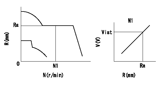
Rack sensor adjustment
1. Flange type rack sensor (rack sensor adjustment -5*20)
(1)These types of rack sensors do not need adjustment. Confirm the performance with the following procedures.
(2)Mount the rack sensor main body to the pump main body.
(3)Fix the pump lever at full.
(4)At supply voltage V1, pump speed N1 and rack position Ra, confirm that the amp's output voltage is Vist.
(5)Move the pump lever two or three times.
(6)Set again to full.
(7)Confirm that the amplifier output voltage is Vist.
(8)Fix the caution plate to the upper part of the rack sensor.
(For those without the caution plate instructions, make sure the nameplate of the rack sensor carries the "Don't hold here" caution.)
(9)Apply red paint to the rack sensor mounting bolts (2 places).
----------
V1=5+-0.01V N1=1600r/min Ra=R1(12.2)+0.45mm Vist=2.93+-0.28V
----------
----------
V1=5+-0.01V N1=1600r/min Ra=R1(12.2)+0.45mm Vist=2.93+-0.28V
----------
Timing setting
(1)Pump vertical direction
(2)Position of gear's standard threaded hole at No 1 cylinder's beginning of injection
(3)Timing device stamping
(4)At the No 1 cylinder's beginning of injection, align with the aligning mark seen through the bracket's check hole and mark the A/T's bevel C1.
(5)B.T.D.C.: aa
----------
aa=7deg
----------
a=(60deg) b=(85deg)
----------
aa=7deg
----------
a=(60deg) b=(85deg)
Information:
Introduction
1. Type 2 fuel injector. 2. Two piece follower. 3. Nose cone. 4. Nozzle assembly.Tools are now available for the removal and installation of nose cone (3), on type 2 fuel injectors (1), when it is necessary to replace a nozzle assembly (4). Type 2 fuel injectors can be identified by the two piece follower (2).
5. 1U9395 Plate. 6. 1U8701 Socket.Use 1U9395 Plate (5) with the 6V4830 Fixture Group (not shown) and the procedure given in this instruction, for the removal and installation of nozzle assembly (4).Earlier type 2 injectors have a nose cone that has serrations on its exterior. These serrations will be damaged when the nose cone is removed. A damaged nose cone is not to be used again. A 7C9795 Nose Cone is available for use as a replacement for the original nose cone.The 7C9795 Nose Cone has a hexagon shape on its exterior. This nose cone can be installed and tightened using 1U8701 Socket (6). When the 7C9795 Nose Cone is installed, be sure to tighten it according to the procedure given in this instruction.Removal and Installation of Nose Cone and Nozzle Assembly
1. Remove the original plate from the 6V4830 Fixture Group and install 1U9395 Plate (1).2. Put injector (2) in position on the fixture group. If the exterior of the injector nose cone is a hexagon shape as shown at location (A), use the 1U8701 Socket for nose cone removal. 3. If the exterior of the nose cone has serrations as shown at location (B), use a pipe wrench, as shown, to remove the nose cone. Anytime a pipe wrench is used to remove a nose cone, the nose cone will be damaged. Never use or install a damaged nose cone on an injector. Always install a new 7C9795 Nose Cone as a replacement. 4. After the nose cone has been loosened, use a hammer and 6V4822 Tip Driver (3) to tap the nozzle assembly as shown. This is done to break the connection between the nozzle assembly and the nose cone. Be sure to use only the 6V4822 Tip Driver in this procedure, because use of a standard punch, or any other similar tool will cause damage to the nozzle tip.5. Remove the nose cone and nozzle assembly. 6. Inspect surface (C) in the injector. This is the sealing surface for the nozzle assembly. This surface must be clean and free of any scratches, nicks or burrs. Even a piece of lint from a shop towel can cause a leak and destroy nozzle performance. 7. Remove original O-ring seal (4). Install a new O-ring seal, refer to the Parts Book for the correct part number. Make sure the O-ring seal is not damaged during installation.Use a generous amount of 1P0808 Grease, or a good grade of multi-purpose lubricant, to lubricate the O-ring seal before the nose cone is installed.8. Install new nozzle assembly (5) on the injector. 9. Install and finger tighten the new 7C9795 Nose Cone on the injector. Using a
Have questions with 101401-7050?
Group cross 101401-7050 ZEXEL
Isuzu
Isuzu
Nissan
Isuzu
Isuzu
Isuzu
101401-7050
INJECTION-PUMP ASSEMBLY