Information injection-pump assembly
ZEXEL
101401-7020
1014017020
NISSAN
1670089TA9
1670089ta9
Rating:
Service parts 101401-7020 INJECTION-PUMP ASSEMBLY:
1.
_
6.
COUPLING PLATE
7.
COUPLING PLATE
8.
_
9.
_
11.
Nozzle and Holder
8-97119-812-0
12.
Open Pre:MPa(Kqf/cm2)
18.1{185}
15.
NOZZLE SET
Cross reference number
ZEXEL
101401-7020
1014017020
NISSAN
1670089TA9
1670089ta9
Zexel num
Bosch num
Firm num
Name
Calibration Data:
Adjustment conditions
Test oil
1404 Test oil ISO4113 or {SAEJ967d}
1404 Test oil ISO4113 or {SAEJ967d}
Test oil temperature
degC
40
40
45
Nozzle and nozzle holder
105780-8140
Bosch type code
EF8511/9A
Nozzle
105780-0000
Bosch type code
DN12SD12T
Nozzle holder
105780-2080
Bosch type code
EF8511/9
Opening pressure
MPa
17.2
Opening pressure
kgf/cm2
175
Injection pipe
Outer diameter - inner diameter - length (mm) mm 6-2-600
Outer diameter - inner diameter - length (mm) mm 6-2-600
Overflow valve
131424-4920
Overflow valve opening pressure
kPa
127
107
147
Overflow valve opening pressure
kgf/cm2
1.3
1.1
1.5
Tester oil delivery pressure
kPa
157
157
157
Tester oil delivery pressure
kgf/cm2
1.6
1.6
1.6
Direction of rotation (viewed from drive side)
Left L
Left L
Injection timing adjustment
Direction of rotation (viewed from drive side)
Left L
Left L
Injection order
1-3-4-2
Pre-stroke
mm
4.1
4.05
4.15
Rack position
Point A R=A
Point A R=A
Beginning of injection position
Governor side NO.1
Governor side NO.1
Difference between angles 1
Cal 1-3 deg. 90 89.5 90.5
Cal 1-3 deg. 90 89.5 90.5
Difference between angles 2
Cal 1-4 deg. 180 179.5 180.5
Cal 1-4 deg. 180 179.5 180.5
Difference between angles 3
Cyl.1-2 deg. 270 269.5 270.5
Cyl.1-2 deg. 270 269.5 270.5
Injection quantity adjustment
Adjusting point
-
Rack position
11.3
Pump speed
r/min
960
960
960
Average injection quantity
mm3/st.
68.5
66.9
70.1
Max. variation between cylinders
%
0
-4
4
Basic
*
Fixing the rack
*
Standard for adjustment of the maximum variation between cylinders
*
Injection quantity adjustment_02
Adjusting point
H
Rack position
9.6+-0.5
Pump speed
r/min
285
285
285
Average injection quantity
mm3/st.
10.5
9.2
11.8
Max. variation between cylinders
%
0
-14
14
Fixing the rack
*
Standard for adjustment of the maximum variation between cylinders
*
Injection quantity adjustment_03
Adjusting point
A
Rack position
R1(11.3)
Pump speed
r/min
960
960
960
Average injection quantity
mm3/st.
68.5
67.5
69.5
Basic
*
Fixing the lever
*
Injection quantity adjustment_04
Adjusting point
B
Rack position
R1-0.05
Pump speed
r/min
1600
1600
1600
Average injection quantity
mm3/st.
78.5
74.5
82.5
Fixing the lever
*
Timer adjustment
Pump speed
r/min
1050--
Advance angle
deg.
0
0
0
Remarks
Start
Start
Timer adjustment_02
Pump speed
r/min
1000
Advance angle
deg.
0.5
Timer adjustment_03
Pump speed
r/min
1600
Advance angle
deg.
5
4.5
5.5
Remarks
Finish
Finish
Test data Ex:
Governor adjustment
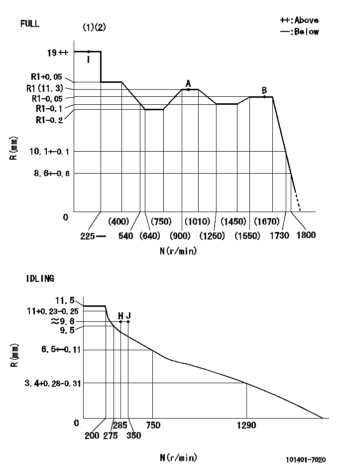
N:Pump speed
R:Rack position (mm)
(1)Torque cam stamping: T1
(2)Tolerance for racks not indicated: +-0.05mm.
----------
T1=K37
----------
----------
T1=K37
----------
Speed control lever angle
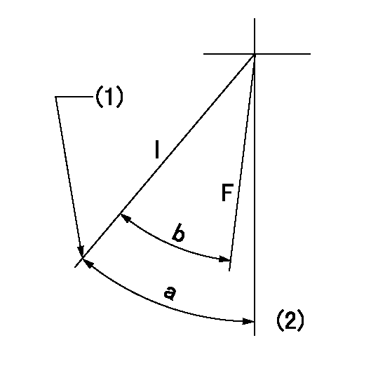
F:Full speed
I:Idle
(1)Stopper bolt set position 'H'
(2)-
----------
----------
a=42deg+-5deg b=40deg+-3deg
----------
----------
a=42deg+-5deg b=40deg+-3deg
Stop lever angle
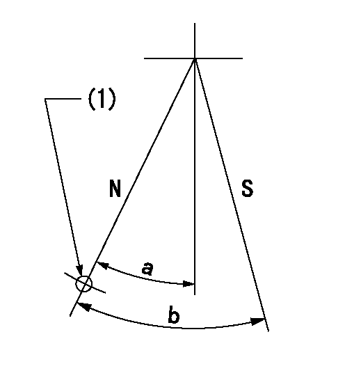
N:Pump normal
S:Stop the pump.
(1)Use the hole at R = aa
----------
aa=64mm
----------
a=20deg+-5deg b=29deg+-5deg
----------
aa=64mm
----------
a=20deg+-5deg b=29deg+-5deg
0000001501 RACK SENSOR
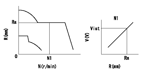
Rack sensor adjustment
1. Flange type rack sensor (rack sensor adjustment -5*20)
(1)These types of rack sensors do not need adjustment. Confirm the performance with the following procedures.
(2)Mount the rack sensor main body to the pump main body.
(3)Fix the pump lever at full.
(4)At supply voltage V1, pump speed N1 and rack position Ra, confirm that the amp's output voltage is Vist.
(5)Move the pump lever two or three times.
(6)Set again to full.
(7)Confirm that the amplifier output voltage is Vist.
(8)Fix the caution plate to the upper part of the rack sensor.
(For those without the caution plate instructions, make sure the nameplate of the rack sensor carries the "Don't hold here" caution.)
(9)Apply red paint to the rack sensor mounting bolts (2 places).
----------
V1=5+-0.01V N1=960r/min Ra=R1(11.3)mm Vist=2.4+-0.28V
----------
----------
V1=5+-0.01V N1=960r/min Ra=R1(11.3)mm Vist=2.4+-0.28V
----------
0000001601 FICD
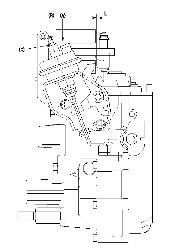
(A) applied negative pressure
(B) Screw
(c) Nut
1. Set the actuator as described below.
(1)Confirm that there is clearance between the actuator lever and the speed lever.
(2)Loosen the nut (C).
(3)Push in the screw (B).
(4)Apply P1 from the actuator (A) part.
(5)Pull out the screw (B) slowly.
(6)Tighten and fix the nut (C) when pump speed is Na and the rack position is Ra.
(7)Torque the nut (C) to T1.
(8)Apply P2 several times.
(9)Confirm that the actuator functions normally.
(10)Confirm that there is a clearance between the actuator lever and the speed lever at that time.
----------
P1=53.3kPa(400mmHg) P2=53.3kPa(400mmHg) Na=440r/min Ra=9.1+-0.1mm T1=1.2~1.6N-m(0.12~0.16kgf-m)
----------
L=(5)mm
----------
P1=53.3kPa(400mmHg) P2=53.3kPa(400mmHg) Na=440r/min Ra=9.1+-0.1mm T1=1.2~1.6N-m(0.12~0.16kgf-m)
----------
L=(5)mm
Timing setting
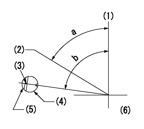
(1)Pump vertical direction
(2)Position of gear's standard threaded hole at No 1 cylinder's beginning of injection
(3)Stamping position on the A/T outer rim
(4)Pump bracket check hole position.
(5)At the No 1 cylinder's beginning of injection, align with the projection seen through the bracket's check hole and mark the A/T's bevel C1.
(6)B.T.D.C.: aa
----------
aa=7deg
----------
a=(60deg) b=(85deg)
----------
aa=7deg
----------
a=(60deg) b=(85deg)
Information:
Connect the wiring harness to a voltage source of 12 VOLTS maximum with a negative ground only. Install the additive tank on the outside of the engine compartment.
Connect the wiring to 8L5000 Switch (1) so that the system can be activated with the starting motor switch in the OFF position. Keep the additive tank full when not in use. This will prevent damage to the system and components by corrosion when not used for long periods of time.Operation: Just before the engine is started, push the switch to activate the system; this will let the additive flow for approximately two minutes, through an orifice connected to the fuel supply line of the Sleeve Metering Fuel System. The fuel transfer pump then pulls the additive into the system along with the Diesel fuel. The system can be again activated if necessary. The engine can be started approximately three to four times per liter (fifteen to twenty times per gallon) of additive.Maintenance: Keep the additive tank full when not in use. This will prevent damage to the system and components by corrosion when not used for long periods of time. Install a new injection group filter (9N3778) at six month intervals or when the filter becomes plugged (full of foreign material) so additive will not flow through it. ADDITIVE RECOMMENDATION: Ethyl D112 Diesel Ignition Improver AVAILABLE SOURCE:U.S.A.
Ethyl Corporation
Distribution Service
Petroleum Chemical Division
451 Florida Boulevard
Baton Rouge, Lousiana 70801
CANADA
Ethyl Corporation of Canada, Ltd.
48 St. Clair Avenue West
Toronto, Ontario, Canada M4V1M7
Order Department
Ethyl D11-2 Diesel Ignition Improver is highly flammable; do not install the additive tank near a source of heat or sparks. If there is a leak in the tank or an accident causes a loss of additive, a fire could be the result.
1 - 9N3334 Tank Assembly2 - 1P4022 Fitting3 - 9N3778 Filter Assembly4 - 8L6557 Connector5 - 317224 Hose Assembly6 - 306984 Connector7 - 9L8791 Solenoid8 - 7W1539 Orifice9 - 8T2543 Tee10 - 5P5009 Reducer11 - 9N3828 Harness Assembly12 - 7G1018 Relay13 - 8L5000 Switch14 - 9N3335 Strap 533567 Bracket15 - 5P0733 Hose 200 (8.0")16 - 1P4278 Clamp17 - 7D1553 Clip18 - 8J1256 Clip19 - 4B1248 Screw 4B2051 Nut 4B4674 Washer20 - 3J7354 Seal21 - 1J9671 Seal1 Install items (12) and (13) inside the operator's compartment; fasten switch (13) on the dash and install relay (12) under the dash. Install additive tank (1) on the outside of the engine compartment in an acceptable location for easy access and away from any source of heat.2 Install 9N3620 Fuel Additive Injection Instruction Film on the dash next to 8L5000 Switch (13). Install 9N3621 CAUTION Film on tank (1) at a location that can be seen from the side of the vehicle.3 Install the remainder of the parts as shown in the above illustration. Fasten filter (3), and hoses (5) and (15) with the clips shown.4 Check the system for leaks after the installation is complete; use air at a maximum pressure of 70 to 105 kPa (10 to 15 psi).
