Information injection-pump assembly
BOSCH
9 400 613 734
9400613734
ZEXEL
101401-7011
1014017011
ISUZU
8971182950
8971182950

Rating:
Include in #1:
101402-2182
as _
Cross reference number
BOSCH
9 400 613 734
9400613734
ZEXEL
101401-7011
1014017011
ISUZU
8971182950
8971182950
Zexel num
Bosch num
Firm num
Name
101401-7011
9 400 613 734
8971182950 ISUZU
INJECTION-PUMP ASSEMBLY
4HG1 * K
4HG1 * K
Calibration Data:
Adjustment conditions
Test oil
1404 Test oil ISO4113 or {SAEJ967d}
1404 Test oil ISO4113 or {SAEJ967d}
Test oil temperature
degC
40
40
45
Nozzle and nozzle holder
105780-8140
Bosch type code
EF8511/9A
Nozzle
105780-0000
Bosch type code
DN12SD12T
Nozzle holder
105780-2080
Bosch type code
EF8511/9
Opening pressure
MPa
17.2
Opening pressure
kgf/cm2
175
Injection pipe
Outer diameter - inner diameter - length (mm) mm 6-2-600
Outer diameter - inner diameter - length (mm) mm 6-2-600
Overflow valve
134424-3920
Overflow valve opening pressure
kPa
127
107
147
Overflow valve opening pressure
kgf/cm2
1.3
1.1
1.5
Tester oil delivery pressure
kPa
157
157
157
Tester oil delivery pressure
kgf/cm2
1.6
1.6
1.6
Direction of rotation (viewed from drive side)
Left L
Left L
Injection timing adjustment
Direction of rotation (viewed from drive side)
Left L
Left L
Injection order
1-3-4-2
Pre-stroke
mm
4.1
4.05
4.15
Rack position
Point A R=A
Point A R=A
Beginning of injection position
Governor side NO.1
Governor side NO.1
Difference between angles 1
Cal 1-3 deg. 90 89.5 90.5
Cal 1-3 deg. 90 89.5 90.5
Difference between angles 2
Cal 1-4 deg. 180 179.5 180.5
Cal 1-4 deg. 180 179.5 180.5
Difference between angles 3
Cyl.1-2 deg. 270 269.5 270.5
Cyl.1-2 deg. 270 269.5 270.5
Injection quantity adjustment
Adjusting point
-
Rack position
11.1
Pump speed
r/min
960
960
960
Average injection quantity
mm3/st.
68.5
66.9
70.1
Max. variation between cylinders
%
0
-4
4
Basic
*
Fixing the rack
*
Standard for adjustment of the maximum variation between cylinders
*
Injection quantity adjustment_02
Adjusting point
H
Rack position
9.5+-0.5
Pump speed
r/min
285
285
285
Average injection quantity
mm3/st.
10.5
9.2
11.8
Max. variation between cylinders
%
0
-14
14
Fixing the rack
*
Standard for adjustment of the maximum variation between cylinders
*
Injection quantity adjustment_03
Adjusting point
A
Rack position
R1(11.1)
Pump speed
r/min
960
960
960
Average injection quantity
mm3/st.
68.5
67.5
69.5
Basic
*
Fixing the lever
*
Injection quantity adjustment_04
Adjusting point
B
Rack position
R1+0.55
Pump speed
r/min
1600
1600
1600
Average injection quantity
mm3/st.
89.5
85.5
93.5
Fixing the lever
*
Injection quantity adjustment_05
Adjusting point
C
Rack position
R1-0.2
Pump speed
r/min
520
520
520
Average injection quantity
mm3/st.
47.6
43.6
51.6
Fixing the lever
*
Injection quantity adjustment_06
Adjusting point
D
Rack position
R1+0.15
Pump speed
r/min
1250
1250
1250
Average injection quantity
mm3/st.
76
72
80
Fixing the lever
*
Timer adjustment
Pump speed
r/min
1150--
Advance angle
deg.
0
0
0
Remarks
Start
Start
Timer adjustment_02
Pump speed
r/min
1100
Advance angle
deg.
0.5
Timer adjustment_03
Pump speed
r/min
1600
Advance angle
deg.
6
5.5
6.5
Remarks
Finish
Finish
Test data Ex:
Governor adjustment
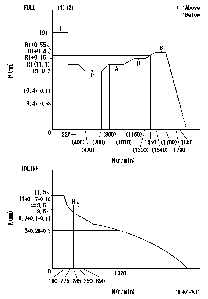
N:Pump speed
R:Rack position (mm)
(1)Torque cam stamping: T1
(2)Tolerance for racks not indicated: +-0.05mm.
----------
T1=N20
----------
----------
T1=N20
----------
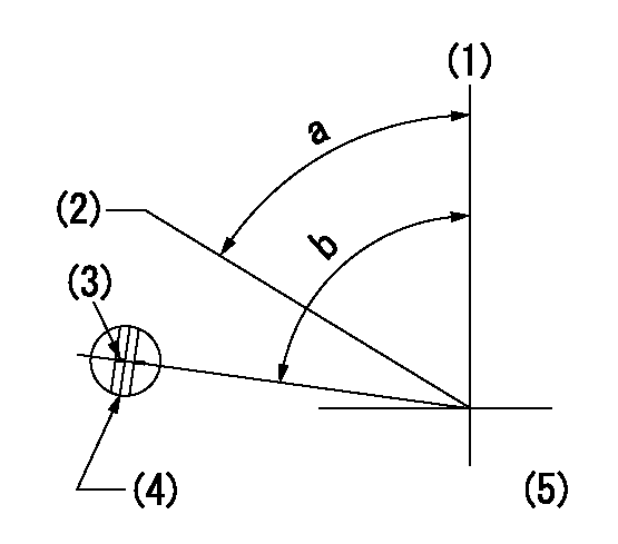
Speed control lever angle
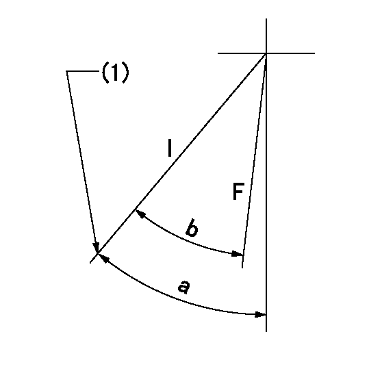
F:Full speed
I:Idle
(1)Stopper bolt set position 'H'
----------
----------
a=43deg+-5deg b=42deg+-3deg
----------
----------
a=43deg+-5deg b=42deg+-3deg
Stop lever angle
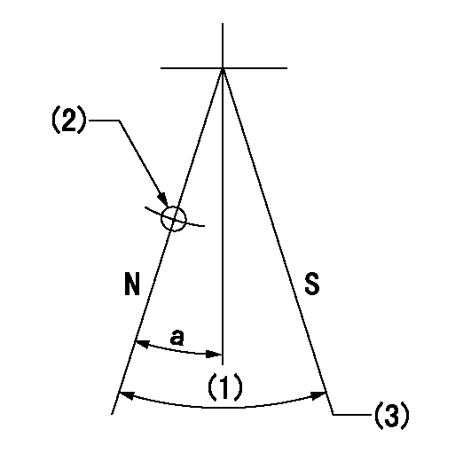
N:Pump normal
S:Stop the pump.
(1)(Actual measurement)
(2)Use the hole at R = aa
(3)At pump speed bb and rack position cc, set the stopper bolt.
----------
aa=25mm bb=1600r/min cc=5.5-0.5mm
----------
a=15deg+-5deg
----------
aa=25mm bb=1600r/min cc=5.5-0.5mm
----------
a=15deg+-5deg
0000001501 FICD
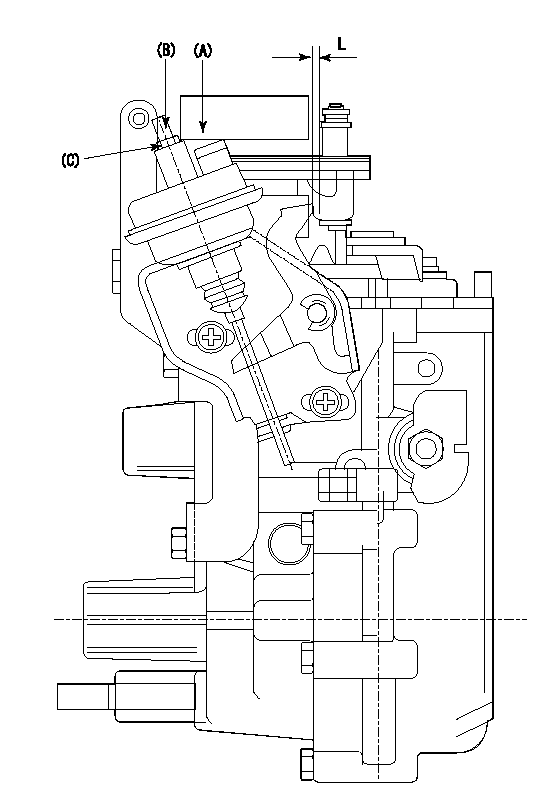
(A) applied negative pressure
(B) Screw
(c) Nut
1. Set the actuator as described below.
(1)Confirm that there is clearance between the actuator lever and the speed lever.
(2)Loosen the nut (C).
(3)Push in the screw (B).
(4)Apply P1 from the actuator (A) part.
(5)Pull out the screw (B) slowly.
(6)Tighten and fix the nut (C) when pump speed is Na and the rack position is Ra.
(7)Torque the nut (C) to T1.
(8)Apply P2 several times.
(9)Confirm that the actuator functions normally.
(10)Confirm that there is a clearance between the actuator lever and the speed lever at that time.
----------
P1=53.3kPa(400mmHg) P2=53.3kPa(400mmHg) Na=400r/min Ra=9.3+-0.1mm T1=1.2~1.6N-m(0.12~0.16kgf-m)
----------
L=(5)mm
----------
P1=53.3kPa(400mmHg) P2=53.3kPa(400mmHg) Na=400r/min Ra=9.3+-0.1mm T1=1.2~1.6N-m(0.12~0.16kgf-m)
----------
L=(5)mm
0000001601 RACK SENSOR
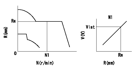
Rack sensor adjustment
1. Flange type rack sensor (rack sensor adjustment -5*20)
(1)These types of rack sensors do not need adjustment. Confirm the performance with the following procedures.
(2)Mount the rack sensor main body to the pump main body.
(3)Fix the pump lever at full.
(4)At supply voltage V1, pump speed N1 and rack position Ra, confirm that the amp's output voltage is Vist.
(5)Move the pump lever two or three times.
(6)Set again to full.
(7)Confirm that the amplifier output voltage is Vist.
(8)Fix the caution plate to the upper part of the rack sensor.
(For those without the caution plate instructions, make sure the nameplate of the rack sensor carries the "Don't hold here" caution.)
(9)Apply red paint to the rack sensor mounting bolts (2 places).
----------
V1=5+-0.01V N1=960r/min Ra=R1(11.1)mm Vist=2.33+-0.28V
----------
----------
V1=5+-0.01V N1=960r/min Ra=R1(11.1)mm Vist=2.33+-0.28V
----------
Timing setting
(1)Pump vertical direction
(2)Position of gear's standard threaded hole at No 1 cylinder's beginning of injection
(3)Timing device stamping
(4)At the No 1 cylinder's beginning of injection, align with the aligning mark seen through the bracket's check hole and mark the A/T's bevel C1.
(5)B.T.D.C.: aa
----------
aa=7deg
----------
a=(60deg) b=(85deg)
----------
aa=7deg
----------
a=(60deg) b=(85deg)
Information:
This instruction is written for electronic technicians only, and must not be used by service personnel with no training or knowledge of electronics. For repairs that can be done by the Caterpillar Dealer Serviceman, with no knowledge of electronics, see Special Instruction Form SMHS6964 "Using 1P3500 and 2P8280 Injection Timing Groups."As an aid to the technician for troubleshooting the inverter and timing light, the following information is given in this instruction:1. Circuit board illustrations showing the position of each of the components and the test points (T) for using a voltmeter or an oscilloscope.2. Schematics of the electrical circuit so the technician can easily follow the sequence of the circuit.3. Test point values.4. Electrical parts replacement information.5. Timing light calibration procedure.Timing Light
1P3500 And 2P8280 Timing Lights - Electrical Schematic, Test Points And Parts List
Inverter - Electrical Schematic, Test Points And Parts List
There is a two position switch that is marked ADV.-RPM on the side of the 1P3499 Timing Light. When the timing light is in use, operation of the ADV.-RPM switch is as follows:RPM Position
A fuel injection pulse opens the switch in the transducer and starts a positive pulse (TP9) of fixed duration, from the monostable composed of Q2 and Q3. This pulse turns on a transistor switch Q4, allowing current to pass through meter M1, which mechanically averages pulses from an operating engine, and is calibrated to read RPM. Switch S2 grounds the gate of SCR1 to prevent the flash tube from strobing.ADV. Position
A fuel injection pulse again starts a pulse from the monostable. Adjustment of R7, the TIME-ADVANCE control, now determines the pulse duration from the monostable. When R7 is adjusted so that TDC on the damper coincides with the pointer on the block of an operating engine, the monostable pulse duration is exactly the same as the fuel system advance measured in seconds. Transistor switch Q4 again turns on, allowing current to pass through meter M1, causing a meter indicator that is calibrated in degrees of advance instead of seconds.Electrical Calibration Procedure
Before the electrical calibration can be done, the following equipment must be obtained.1) Oscilloscope with triggered sweep. Heath Co. M/N SO-4530 or equivalent.2) Signal generator. Heath M/N SG-72A or equivalent.3) Electronic counter. Data Precision M/N 5740 or equivalent.4) Electronic switch (dealer built).Calibration Procedure
(1) Hold the 1P3499 Timing Light in the same position (about a 45° angle) as if measuring the timing advance on an engine, and check the mechanical meter zero. Make an adjustment to zero if necessary. (2) To remove the protective rubber boot from the flash tube, twist the rubber boot and pull it away from the timing light as shown. (3) Remove the right side (side that has the serial number tag) of the timing light case.(4) Connect the 1P3499 Timing Light to a circuit like the one that follows. This will simulate (be the same as) a fuel flow transducer on an engine that is operating at 2400 RPM. (5) Turn the TIME-ADV. control counterclockwise (CCW) to its minimum
Have questions with 101401-7011?
Group cross 101401-7011 ZEXEL
Isuzu
Isuzu
101401-7011
9 400 613 734
8971182950
INJECTION-PUMP ASSEMBLY
4HG1
4HG1