Information injection-pump assembly
ZEXEL
101401-4940
1014014940
ISUZU
8971153970
8971153970
Rating:
Service parts 101401-4940 INJECTION-PUMP ASSEMBLY:
1.
_
6.
COUPLING PLATE
7.
COUPLING PLATE
8.
_
9.
_
11.
Nozzle and Holder
8-97115-503-1
12.
Open Pre:MPa(Kqf/cm2)
17.7{180}/21.6{220}
14.
NOZZLE
Cross reference number
ZEXEL
101401-4940
1014014940
ISUZU
8971153970
8971153970
Zexel num
Bosch num
Firm num
Name
Calibration Data:
Adjustment conditions
Test oil
1404 Test oil ISO4113 or {SAEJ967d}
1404 Test oil ISO4113 or {SAEJ967d}
Test oil temperature
degC
40
40
45
Nozzle and nozzle holder
105780-8250
Bosch type code
1 688 901 101
Nozzle
105780-0120
Bosch type code
1 688 901 990
Nozzle holder
105780-2190
Opening pressure
MPa
20.7
Opening pressure
kgf/cm2
211
Injection pipe
Outer diameter - inner diameter - length (mm) mm 6-2-600
Outer diameter - inner diameter - length (mm) mm 6-2-600
Overflow valve
134424-3920
Overflow valve opening pressure
kPa
127
107
147
Overflow valve opening pressure
kgf/cm2
1.3
1.1
1.5
Tester oil delivery pressure
kPa
255
255
255
Tester oil delivery pressure
kgf/cm2
2.6
2.6
2.6
Direction of rotation (viewed from drive side)
Left L
Left L
Injection timing adjustment
Direction of rotation (viewed from drive side)
Left L
Left L
Injection order
1-3-4-2
Pre-stroke
mm
3.8
3.75
3.85
Rack position
Point A R=A
Point A R=A
Beginning of injection position
Governor side NO.1
Governor side NO.1
Difference between angles 1
Cal 1-3 deg. 90 89.5 90.5
Cal 1-3 deg. 90 89.5 90.5
Difference between angles 2
Cal 1-4 deg. 180 179.5 180.5
Cal 1-4 deg. 180 179.5 180.5
Difference between angles 3
Cyl.1-2 deg. 270 269.5 270.5
Cyl.1-2 deg. 270 269.5 270.5
Injection quantity adjustment
Adjusting point
-
Rack position
13.1
Pump speed
r/min
1160
1160
1160
Average injection quantity
mm3/st.
97
95.4
98.6
Max. variation between cylinders
%
0
-4
4
Basic
*
Fixing the rack
*
Standard for adjustment of the maximum variation between cylinders
*
Injection quantity adjustment_02
Adjusting point
Z
Rack position
9.7+-0.5
Pump speed
r/min
285
285
285
Average injection quantity
mm3/st.
14.5
13.2
15.8
Max. variation between cylinders
%
0
-14
14
Fixing the rack
*
Standard for adjustment of the maximum variation between cylinders
*
Injection quantity adjustment_03
Adjusting point
A
Rack position
R1(13.1)
Pump speed
r/min
1160
1160
1160
Average injection quantity
mm3/st.
97
96
98
Basic
*
Fixing the lever
*
Boost pressure
kPa
60
60
Boost pressure
mmHg
450
450
Injection quantity adjustment_04
Adjusting point
B
Rack position
R1+0.35
Pump speed
r/min
1450
1450
1450
Average injection quantity
mm3/st.
96.5
92.5
100.5
Fixing the lever
*
Boost pressure
kPa
60
60
Boost pressure
mmHg
450
450
Injection quantity adjustment_05
Adjusting point
C
Rack position
R2-0.45
Pump speed
r/min
700
700
700
Average injection quantity
mm3/st.
86
82
90
Fixing the lever
*
Boost pressure
kPa
0
0
0
Boost pressure
mmHg
0
0
0
Injection quantity adjustment_06
Adjusting point
I
Rack position
-
Pump speed
r/min
150
150
150
Average injection quantity
mm3/st.
95
95
127
Fixing the lever
*
Boost pressure
kPa
0
0
0
Boost pressure
mmHg
0
0
0
Boost compensator adjustment
Pump speed
r/min
700
700
700
Rack position
R2-0.45
Boost pressure
kPa
27.3
26
28.6
Boost pressure
mmHg
205
195
215
Boost compensator adjustment_02
Pump speed
r/min
700
700
700
Rack position
R2(R1-0.
6)
Boost pressure
kPa
46.7
46.7
46.7
Boost pressure
mmHg
350
350
350
Timer adjustment
Pump speed
r/min
1185--
Advance angle
deg.
0
0
0
Remarks
Start
Start
Timer adjustment_02
Pump speed
r/min
1135
Advance angle
deg.
0.5
Timer adjustment_03
Pump speed
r/min
1450
Advance angle
deg.
4.8
4.3
5.3
Timer adjustment_04
Pump speed
r/min
-
Advance angle
deg.
5
4.5
5.5
Remarks
Measure the actual speed, stop
Measure the actual speed, stop
Test data Ex:
Governor adjustment
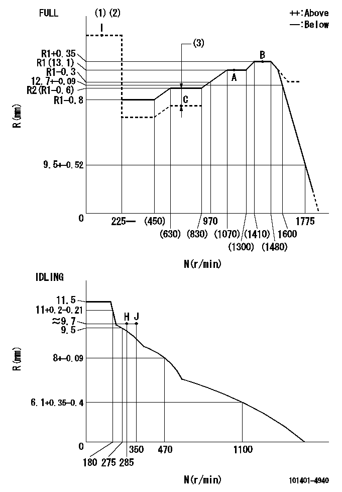
N:Pump speed
R:Rack position (mm)
(1)Torque cam stamping: T1
(2)Tolerance for racks not indicated: +-0.05mm.
(3)Boost compensator stroke: BCL
----------
T1=N23 BCL=0.45+-0.1mm
----------
----------
T1=N23 BCL=0.45+-0.1mm
----------
Speed control lever angle
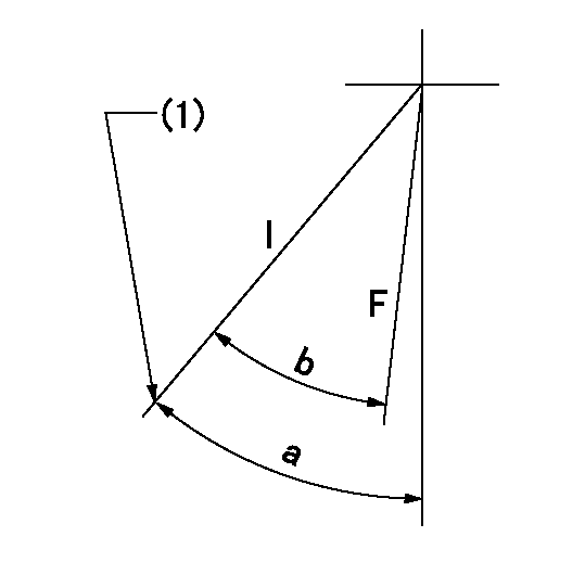
F:Full speed
I:Idle
(1)Stopper bolt set position 'H'
----------
----------
a=42deg+-5deg b=32deg+-3deg
----------
----------
a=42deg+-5deg b=32deg+-3deg
Stop lever angle
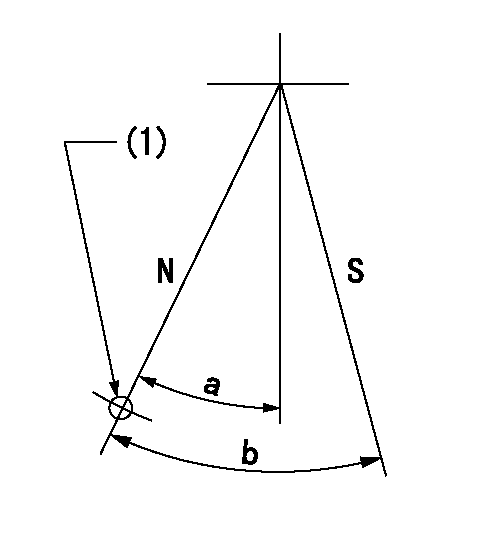
N:Pump normal
S:Stop the pump.
(1)Use the hole at R = aa
----------
aa=64mm
----------
a=20deg+-5deg b=29deg+-5deg
----------
aa=64mm
----------
a=20deg+-5deg b=29deg+-5deg
0000001501 FICD
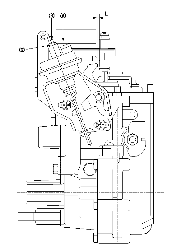
(A) applied negative pressure
(B) Screw
(c) Nut
1. Set the actuator as described below.
(1)Confirm that there is clearance between the actuator lever and the speed lever.
(2)Loosen the nut (C).
(3)Push in the screw (B).
(4)Apply P1 from the actuator (A) part.
(5)Pull out the screw (B) slowly.
(6)Tighten and fix the nut (C) when pump speed is Na and the rack position is Ra.
(7)Torque the nut (C) to T1.
(8)Apply P2 several times.
(9)Confirm that the actuator functions normally.
(10)Confirm that there is a clearance between the actuator lever and the speed lever at that time.
----------
P1=53.3kPa(400mmHg) P2=53.3kPa(400mmHg) Na=410r/min Ra=9.75+-0.1mm T1=1.2~1.6N-m(0.12~0.16kgf-m)
----------
L=(5)mm
----------
P1=53.3kPa(400mmHg) P2=53.3kPa(400mmHg) Na=410r/min Ra=9.75+-0.1mm T1=1.2~1.6N-m(0.12~0.16kgf-m)
----------
L=(5)mm
Timing setting
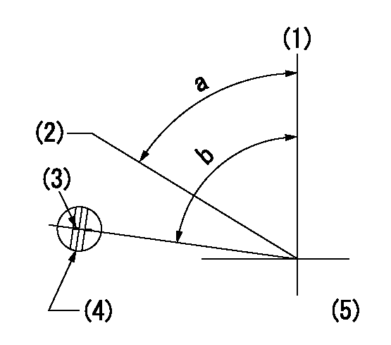
(1)Pump vertical direction
(2)Position of gear's standard threaded hole at No 1 cylinder's beginning of injection
(3)Stamping position on the A/T outer rim
(4)At the No 1 cylinder's beginning of injection, align with the aligning mark seen through the bracket's check hole and mark the A/T's bevel C1.
(5)B.T.D.C.: aa
----------
aa=6deg
----------
a=(60deg) b=(85deg)
----------
aa=6deg
----------
a=(60deg) b=(85deg)
Information:
Caterpillar Diesel Engines can operate effectively in cold weather. However, engine operation in cold weather is dependent on the type of fuel used and how well the fuel moves through fuel related components. The purpose of this section is to explain some of the problems and steps that can be taken to minimize fuel problems during cold weather operation, when the engine area is colder than 5°C (40°F).Radiator Restrictions
Caterpillar discourages the use of air flow restriction devices mounted in front of radiators with air-to-air aftercooled engines. Air flow restriction can cause higher exhaust temperatures, power loss, excessive fan usage, and a reduction in fuel economy.If an air flow restriction device must be used, the device should have a permanent opening directly in line with the fan hub. The device must have a minimum opening dimension of at least 770 cm2 (120 in2).A centered opening, directly in line with the fan hub, is specified to provide sensing when viscous fan drives are used and/or to prevent an interrupted air flow on the fan blades. Interrupted air flow on the fan blades could cause a fan failure.Caterpillar recommends that a package include an intake manifold temperature device, such as a light indicator, buzzer, etc., set at 65°C (150°F) and/or installation of an inlet air temperature gauge. For the ATAAC engines, air temperature in the intake manifold should not exceed 65°C (150°F). Temperatures exceeding this limit can cause power loss and potential engine damage.This temperature provides engine protection for full restriction device closure. This temperature can also serve as a diagnostic tool for a malfunction of the charge air cooling system. It is not anticipated that a temperature of 65°C (150°F) will be encountered under normal operating conditions.Fuel and the Effect from Cold Weather
The two types of diesel fuel available for your engine are typically grades No. 1 and No.2. No. 2 diesel fuel is the most commonly used fuel. No. 1 diesel fuel, or a blend of No. 1 and No. 2, is best suited for cold weather operation.Quantities of No. 1 diesel fuel are limited, and generally only available during the winter months in the colder climates. During cold weather operation, if No. 1 fuel is unavailable, it may be necessary to use No. 2 diesel fuel.There are three major differences between No. 1 and No. 2 diesel fuel. No. 1 diesel fuel has:* a lower cloud point* a lower pour point* a lower BTU (kJ) (heat content) rating per unit volume of fuel than the average No. 2 diesel fuel.When using No. 1 diesel fuel, you may notice a drop in power and fuel efficiency. You should not experience any other operating effects.The cloud point is the temperature at which a cloud or haze of wax crystals begins to form in the fuel and cause fuel filters to plug. The pour point is the temperature which diesel fuel begins to thicken and be more resistant to flow through fuel pumps and lines.Be aware of these fuel values when