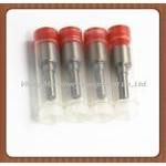
Information injection-pump assembly
BOSCH
F 019 Z10 100
f019z10100
ZEXEL
101401-4630
1014014630
ISUZU
8970903600
8970903600
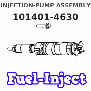
Rating:
Service parts 101401-4630 INJECTION-PUMP ASSEMBLY:
1.
_
6.
COUPLING PLATE
7.
COUPLING PLATE
8.
_
9.
_
11.
Nozzle and Holder
8-97114-016-0
12.
Open Pre:MPa(Kqf/cm2)
18.1{185}
15.
NOZZLE SET
Cross reference number
BOSCH
F 019 Z10 100
f019z10100
ZEXEL
101401-4630
1014014630
ISUZU
8970903600
8970903600
Zexel num
Bosch num
Firm num
Name
101401-4630
F 019 Z10 100
8970903600 ISUZU
INJECTION-PUMP ASSEMBLY
4HF1 * K
4HF1 * K
Calibration Data:
Adjustment conditions
Test oil
1404 Test oil ISO4113 or {SAEJ967d}
1404 Test oil ISO4113 or {SAEJ967d}
Test oil temperature
degC
40
40
45
Nozzle and nozzle holder
105780-8140
Bosch type code
EF8511/9A
Nozzle
105780-0000
Bosch type code
DN12SD12T
Nozzle holder
105780-2080
Bosch type code
EF8511/9
Opening pressure
MPa
17.2
Opening pressure
kgf/cm2
175
Injection pipe
Outer diameter - inner diameter - length (mm) mm 6-2-600
Outer diameter - inner diameter - length (mm) mm 6-2-600
Overflow valve
131424-4920
Overflow valve opening pressure
kPa
127
107
147
Overflow valve opening pressure
kgf/cm2
1.3
1.1
1.5
Tester oil delivery pressure
kPa
157
157
157
Tester oil delivery pressure
kgf/cm2
1.6
1.6
1.6
Direction of rotation (viewed from drive side)
Left L
Left L
Injection timing adjustment
Direction of rotation (viewed from drive side)
Left L
Left L
Injection order
1-3-4-2
Pre-stroke
mm
4.1
4.05
4.15
Rack position
Point A R=A
Point A R=A
Beginning of injection position
Governor side NO.1
Governor side NO.1
Difference between angles 1
Cal 1-3 deg. 90 89.5 90.5
Cal 1-3 deg. 90 89.5 90.5
Difference between angles 2
Cal 1-4 deg. 180 179.5 180.5
Cal 1-4 deg. 180 179.5 180.5
Difference between angles 3
Cyl.1-2 deg. 270 269.5 270.5
Cyl.1-2 deg. 270 269.5 270.5
Injection quantity adjustment
Adjusting point
-
Rack position
11.4
Pump speed
r/min
960
960
960
Average injection quantity
mm3/st.
74.7
73.1
76.3
Max. variation between cylinders
%
0
-2.5
2.5
Basic
*
Fixing the rack
*
Standard for adjustment of the maximum variation between cylinders
*
Injection quantity adjustment_02
Adjusting point
H
Rack position
10+-0.5
Pump speed
r/min
285
285
285
Average injection quantity
mm3/st.
23.5
22.2
24.8
Max. variation between cylinders
%
0
-14
14
Fixing the rack
*
Standard for adjustment of the maximum variation between cylinders
*
Injection quantity adjustment_03
Adjusting point
A
Rack position
R1(11.4)
Pump speed
r/min
960
960
960
Average injection quantity
mm3/st.
74.7
73.7
75.7
Basic
*
Fixing the lever
*
Injection quantity adjustment_04
Adjusting point
B
Rack position
R1+0.25
Pump speed
r/min
1600
1600
1600
Average injection quantity
mm3/st.
89.8
85.8
93.8
Fixing the lever
*
Injection quantity adjustment_05
Adjusting point
I
Rack position
-
Pump speed
r/min
150
150
150
Average injection quantity
mm3/st.
76
76
108
Fixing the lever
*
Timer adjustment
Pump speed
r/min
1375--
Advance angle
deg.
0
0
0
Remarks
Start
Start
Timer adjustment_02
Pump speed
r/min
1325
Advance angle
deg.
0.3
Timer adjustment_03
Pump speed
r/min
1500
Advance angle
deg.
3.3
2.8
3.8
Timer adjustment_04
Pump speed
r/min
1600--
Advance angle
deg.
5
4.5
5.5
Remarks
Finish
Finish
Test data Ex:
Governor adjustment
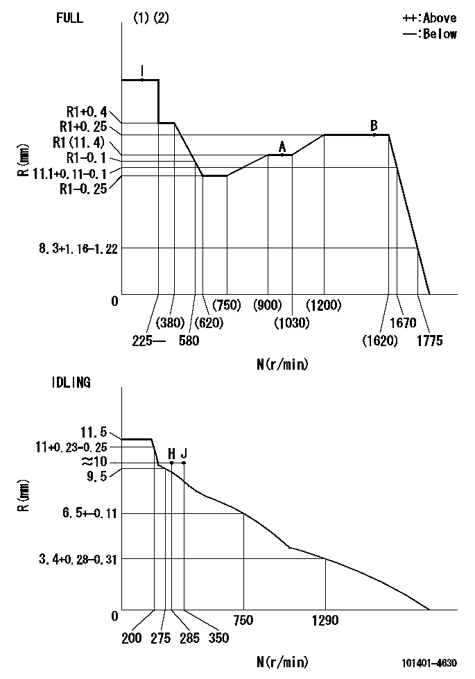
N:Pump speed
R:Rack position (mm)
(1)Torque cam stamping: T1
(2)Tolerance for racks not indicated: +-0.05mm.
----------
T1=H58
----------
----------
T1=H58
----------
Speed control lever angle
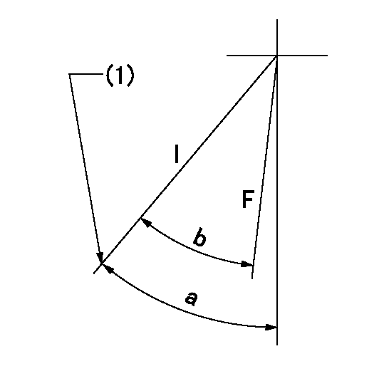
F:Full speed
I:Idle
(1)Stopper bolt set position 'H'
----------
----------
a=41deg+-5deg b=(37deg)+-3deg
----------
----------
a=41deg+-5deg b=(37deg)+-3deg
Stop lever angle
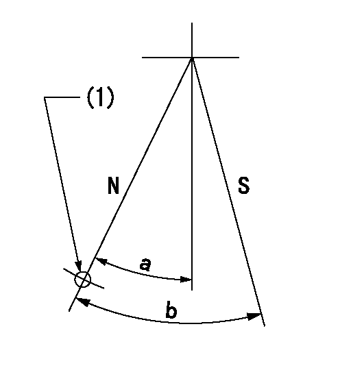
N:Pump normal
S:Stop the pump.
(1)Use the hole at R = aa
----------
aa=64mm
----------
a=20deg+-5deg b=29deg+-5deg
----------
aa=64mm
----------
a=20deg+-5deg b=29deg+-5deg
0000001501 FICD
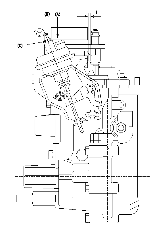
(A) applied negative pressure
(B) Screw
(c) Nut
1. Set the actuator as described below.
(1)Confirm that there is clearance between the actuator lever and the speed lever.
(2)Loosen the nut (C).
(3)Push in the screw (B).
(4)Apply P1 from the actuator (A) part.
(5)Pull out the screw (B) slowly.
(6)Tighten and fix the nut (C) when pump speed is Na and the rack position is Ra.
(7)Torque the nut (C) to T1.
(8)Apply P2 several times.
(9)Confirm that the actuator functions normally.
(10)Confirm that there is a clearance between the actuator lever and the speed lever at that time.
----------
P1=53.3kPa(400mmHg) P2=53.3kPa(400mmHg) Na=540r/min Ra=9.55+-0.1mm T1=1.2~1.6N-m(0.12~0.16kgf-m)
----------
L=(2)mm
----------
P1=53.3kPa(400mmHg) P2=53.3kPa(400mmHg) Na=540r/min Ra=9.55+-0.1mm T1=1.2~1.6N-m(0.12~0.16kgf-m)
----------
L=(2)mm
0000001601 MICRO SWITCH
Adjustment of the micro-switch
Adjust the bolt to obtain the following lever position when the micro-switch is ON.
(1)Speed N1
(2)Rack position Ra
----------
N1=1100r/min Ra=9.2+-0.1mm
----------
----------
N1=1100r/min Ra=9.2+-0.1mm
----------
Timing setting
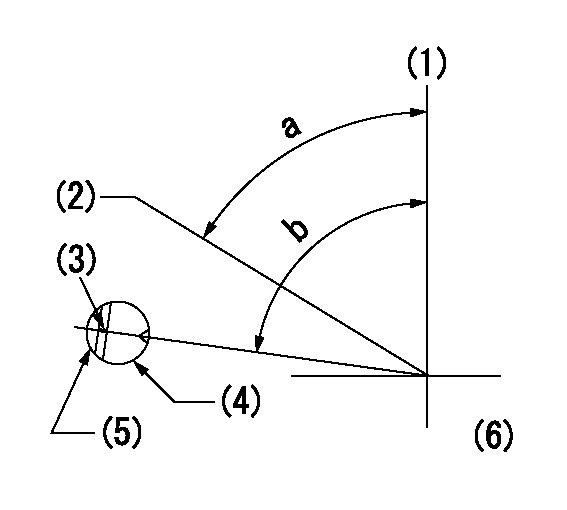
(1)Pump vertical direction
(2)Position of gear's standard threaded hole at No 1 cylinder's beginning of injection
(3)Stamping position on the A/T outer rim
(4)Pump bracket check hole position.
(5)At the No 1 cylinder's beginning of injection, align with the projection seen through the bracket's check hole and mark the A/T's bevel C1.
(6)B.T.D.C.: aa
----------
aa=10deg
----------
a=(60deg) b=(85deg)
----------
aa=10deg
----------
a=(60deg) b=(85deg)
Information:
Radiator Fins, Aftercooler,Belts, and Hoses
Inspect/Check Radiator Fins
Check the radiator fins for debris. High pressure water is an excellent way to clean the debris out of the radiator fins. If necessary, use a light bulb behind the radiator fins to see if they are completely clean.Refer to Know Your Cooling System, SEBD0518, for more detailed information on cleaning your radiator fins.Inspect/Check Aftercooler System
A hose failure or significant system leak will cause a large drop in boost pressure and power. The engine can be operated at this power level long enough to reach a safe stop or repair area. Sustained operation under this condition should be avoided.
Inspect the front of the air-to-air aftercooler. Examine core fins for external damage, insects, dirt, debris, salt, corrosion, etc. Use a firm stainless steel brush and soapy water to remove dirt, debris, salt, etc. Depending on your findings and operating environment, the maintenance interval for cleaning the air-to-air aftercooler may be more frequent.A slight reduction in power or response, or a small increase in exhaust temperature, may indicate a small air leak in the charge air cooler core or piping. Inspect all air ducting and gasket connections at each oil change. Constant torque hose clamps should be secure. Tighten these clamps until the spring is at least partially compressed.Inspect all welds for cracks. Check the mounting brackets to ensure they are secure and in good condition. Whenever air-to-air aftercooler parts are repaired and/or replaced, a leak test is highly recommended. Refer to the service manual or consult your Caterpillar dealer for the correct procedure to use when performing a leak test.Inspect/Adjust Belts
Inspect the condition and adjustment of alternator belts and fan drive belts.Inspect all drive belts for wear and replace if they show any signs of wear.If one belt in a set requires replacement, always install a new matched set of belts. Never replace just the worn belt. If only the worn belt is replaced, the new belt will carry all the load, as it will not be stretched as much as the older belts. All the belts will fail in rapid succession.If belts are too loose, they vibrate enough to cause unnecessary wear on the belts and pulleys. If belts are too tight, unnecessary stresses are placed upon the pulley bearings and belts which might shorten the life of both.1. Inspect the condition and adjustment of alternator belts and fan drive belts.2. To check the belt tension, apply 110 N (25 lbs) of force midway between the pulleys. Correctly adjusted belts will deflect 13 to 19 mm (1/2 to 3/4 inch).Adjust Alternator Belts
3. To adjust the alternator drive
Have questions with 101401-4630?
Group cross 101401-4630 ZEXEL
Isuzu
Isuzu
101401-4630
F 019 Z10 100
8970903600
INJECTION-PUMP ASSEMBLY
4HF1
4HF1
