Information injection-pump assembly
ZEXEL
101401-4402
1014014402
ISUZU
8970613923
8970613923
Rating:
Service parts 101401-4402 INJECTION-PUMP ASSEMBLY:
1.
_
6.
COUPLING PLATE
7.
COUPLING PLATE
8.
_
9.
_
11.
Nozzle and Holder
8-97114-315-1
12.
Open Pre:MPa(Kqf/cm2)
17.7{180}/21.6{220}
14.
NOZZLE
Cross reference number
ZEXEL
101401-4402
1014014402
ISUZU
8970613923
8970613923
Zexel num
Bosch num
Firm num
Name
Calibration Data:
Adjustment conditions
Test oil
1404 Test oil ISO4113 or {SAEJ967d}
1404 Test oil ISO4113 or {SAEJ967d}
Test oil temperature
degC
40
40
45
Nozzle and nozzle holder
105780-8140
Bosch type code
EF8511/9A
Nozzle
105780-0000
Bosch type code
DN12SD12T
Nozzle holder
105780-2080
Bosch type code
EF8511/9
Opening pressure
MPa
17.2
Opening pressure
kgf/cm2
175
Injection pipe
Outer diameter - inner diameter - length (mm) mm 6-2-600
Outer diameter - inner diameter - length (mm) mm 6-2-600
Overflow valve
134424-4920
Overflow valve opening pressure
kPa
127
107
147
Overflow valve opening pressure
kgf/cm2
1.3
1.1
1.5
Tester oil delivery pressure
kPa
157
157
157
Tester oil delivery pressure
kgf/cm2
1.6
1.6
1.6
Direction of rotation (viewed from drive side)
Left L
Left L
Injection timing adjustment
Direction of rotation (viewed from drive side)
Left L
Left L
Injection order
1-3-4-2
Pre-stroke
mm
3.8
3.75
3.85
Rack position
Point A R=A
Point A R=A
Beginning of injection position
Governor side NO.1
Governor side NO.1
Difference between angles 1
Cal 1-3 deg. 90 89.5 90.5
Cal 1-3 deg. 90 89.5 90.5
Difference between angles 2
Cal 1-4 deg. 180 179.5 180.5
Cal 1-4 deg. 180 179.5 180.5
Difference between angles 3
Cyl.1-2 deg. 270 269.5 270.5
Cyl.1-2 deg. 270 269.5 270.5
Injection quantity adjustment
Adjusting point
-
Rack position
13.2
Pump speed
r/min
1200
1200
1200
Average injection quantity
mm3/st.
93
91.4
94.6
Max. variation between cylinders
%
0
-2.5
2.5
Basic
*
Fixing the rack
*
Standard for adjustment of the maximum variation between cylinders
*
Injection quantity adjustment_02
Adjusting point
Z
Rack position
9.7+-0.5
Pump speed
r/min
400
400
400
Average injection quantity
mm3/st.
14.5
13.2
15.8
Max. variation between cylinders
%
0
-14
14
Fixing the rack
*
Standard for adjustment of the maximum variation between cylinders
*
Injection quantity adjustment_03
Adjusting point
A
Rack position
R1(13.2)
Pump speed
r/min
1200
1200
1200
Average injection quantity
mm3/st.
93
92
94
Basic
*
Fixing the lever
*
Boost pressure
kPa
62
62
Boost pressure
mmHg
465
465
Injection quantity adjustment_04
Adjusting point
B
Rack position
R1+0.25
Pump speed
r/min
1450
1450
1450
Average injection quantity
mm3/st.
95.5
91.5
99.5
Fixing the lever
*
Boost pressure
kPa
62
62
Boost pressure
mmHg
465
465
Injection quantity adjustment_05
Adjusting point
C
Rack position
R2-0.6
Pump speed
r/min
700
700
700
Average injection quantity
mm3/st.
75
71
79
Fixing the lever
*
Boost pressure
kPa
0
0
0
Boost pressure
mmHg
0
0
0
Injection quantity adjustment_06
Adjusting point
I
Rack position
-
Pump speed
r/min
150
150
150
Average injection quantity
mm3/st.
55
55
87
Fixing the lever
*
Boost pressure
kPa
0
0
0
Boost pressure
mmHg
0
0
0
Boost compensator adjustment
Pump speed
r/min
700
700
700
Rack position
R2-0.6
Boost pressure
kPa
26.7
25.4
28
Boost pressure
mmHg
200
190
210
Boost compensator adjustment_02
Pump speed
r/min
700
700
700
Rack position
R2(R1-0.
55)
Boost pressure
kPa
48.7
48.7
48.7
Boost pressure
mmHg
365
365
365
Timer adjustment
Pump speed
r/min
1250--
Advance angle
deg.
0
0
0
Remarks
Start
Start
Timer adjustment_02
Pump speed
r/min
1200
Advance angle
deg.
0.5
Timer adjustment_03
Pump speed
r/min
1450
Advance angle
deg.
3.8
3.3
4.3
Timer adjustment_04
Pump speed
r/min
-
Advance angle
deg.
4
3.5
4.5
Remarks
Measure the actual speed, stop
Measure the actual speed, stop
Test data Ex:
Governor adjustment
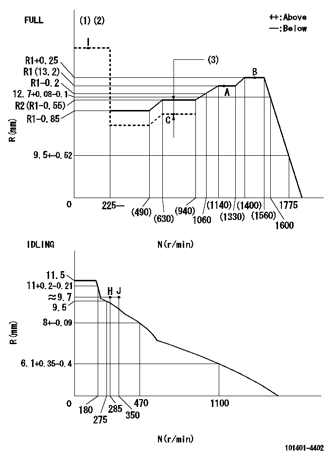
N:Pump speed
R:Rack position (mm)
(1)Torque cam stamping: T1
(2)Tolerance for racks not indicated: +-0.05mm.
(3)Boost compensator stroke: BCL
----------
T1=J03 BCL=0.6+-0.1mm
----------
----------
T1=J03 BCL=0.6+-0.1mm
----------
Speed control lever angle
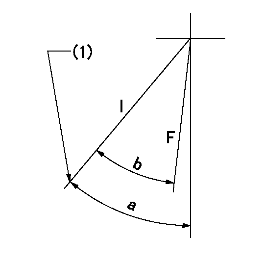
F:Full speed
I:Idle
(1)Stopper bolt set position 'H'
----------
----------
a=42deg+-5deg b=32deg+-3deg
----------
----------
a=42deg+-5deg b=32deg+-3deg
Stop lever angle
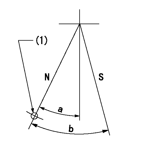
N:Pump normal
S:Stop the pump.
(1)Use the hole at R = aa
----------
aa=64mm
----------
a=20deg+-5deg b=29deg+-5deg
----------
aa=64mm
----------
a=20deg+-5deg b=29deg+-5deg
0000001501 MICRO SWITCH
Adjustment of the micro-switch
Adjust the bolt to obtain the following lever position when the micro-switch is ON.
(1)Speed N1
(2)Rack position Ra
----------
N1=1100r/min Ra=9.4+-0.1mm
----------
----------
N1=1100r/min Ra=9.4+-0.1mm
----------
0000001601 FICD
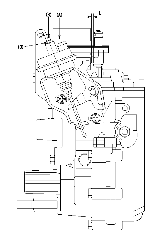
(A) applied negative pressure
(B) Screw
(c) Nut
1. Set the actuator as described below.
(1)Confirm that there is clearance between the actuator lever and the speed lever.
(2)Loosen the nut (C).
(3)Push in the screw (B).
(4)Apply P1 from the actuator (A) part.
(5)Pull out the screw (B) slowly.
(6)Tighten and fix the nut (C) when pump speed is Na and the rack position is Ra.
(7)Torque the nut (C) to T1.
(8)Apply P2 several times.
(9)Confirm that the actuator functions normally.
(10)Confirm that there is a clearance between the actuator lever and the speed lever at that time.
----------
P1=53.3kPa(400mmHg) P2=53.3kPa(400mmHg) Na=475r/min Ra=9.75+-0.1mm T1=1.2~1.6N-m(0.12~0.16kgf-m)
----------
L=(2)mm
----------
P1=53.3kPa(400mmHg) P2=53.3kPa(400mmHg) Na=475r/min Ra=9.75+-0.1mm T1=1.2~1.6N-m(0.12~0.16kgf-m)
----------
L=(2)mm
Timing setting
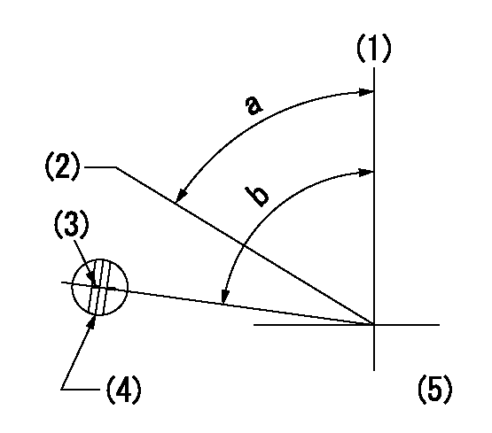
(1)Pump vertical direction
(2)Position of gear's standard threaded hole at No 1 cylinder's beginning of injection
(3)Stamping position on the A/T outer rim
(4)At the No 1 cylinder's beginning of injection, align with the aligning mark seen through the bracket's check hole and mark the A/T's bevel C1.
(5)B.T.D.C.: aa
----------
aa=9deg
----------
a=(60deg) b=(85deg)
----------
aa=9deg
----------
a=(60deg) b=(85deg)
Information:
Do not engage starter when flywheel is turning.Do not start engine under load.
Above 0°C (32°F)
1. Place the transmission or other power takeoff attachments in NEUTRAL. For air start systems; check the air supply before starting the engine. There must be 690 kPa (100 psi) air pressure available.2. Move governor control lever (throttle) or depress the accelerator to half engine speed position.3. Turn the battery disconnect switch (if equipped) to the ON position. 4. Push the air start knob (1) IN, or ... ... turn the start switch (2) for marine, industrial and generator set engines or ... ... turn the start switch (3) for machines (vehicles) to the START position.
Do not crank the engine for more than 30 seconds. Allow 2 minutes for the starter to cool before cranking again. If oil pressure does not rise within 15 seconds after the engine starts, stop the engine and make necessary corrections.
5. Release the start switch or air start knob when the engine starts.6. Do not apply load to the engine or increase engine speed until oil pressure and all temperature gauges reach operating temperature. Check all gauges during the warm-up period.Below 0°C (32°F)
Ether is poisonous and flammable.Do not store replacement cylinders in living areas or in the operator's compartment.Do not smoke while changing ether cylinders.Use ether only in well ventilated areas.Use it with care to avoid fires.Avoid breathing of the vapors or repeated contact of ether with skin.Do not puncture or burn cylinders.Discard cylinders in a safe place.Keep ether container away from heat, sparks, open flame, or open sunlight. It may explode.Do not store replacement cylinders at temperatures above 49°C (120°F).Do not use cylinders in environments above 93°C (200°F).
1. Depress ether switch and hold for 3 seconds, then release. For air start system; check the air supply before starting the engine. There must be 690 kPa (100 psi) air pressure available.2. Push the air start knob IN or turn the start switch for engines, or turn the start switch for machines (vehicles) to the START position.3. Begin cranking the engine, and depress ether switch and hold for 3 seconds then release. Additional injections of ether may be required to start and/or achieve low idle speed.4. Operate the engine at low speed and/or load until all systems reach operating temperatures. Check all gauges during the warmup period.
Do not use excessive starting fluid during starting or after the engine is running. Do not crank the engine for more than 30 seconds. Allow 2 minutes for the starter motor to cool before cranking again.If oil pressure does not rise within 15 seconds after the engine starts, stop the engine and make necessary corrections.
Turn the battery disconnect switch (if equipped) OFF after the engine is stopped to prevent battery discharge while starter motor is cooling.For starting below -18°C (0°F), use of optional cold weather starting aids are recommended. A coolant heater or extra battery capacity may be required.For temperatures below -23°C (-10°F), consult your Caterpillar dealer or refer to the "Cold Weather Operation