Information injection-pump assembly
ZEXEL
101401-2410
1014012410
HINO
220206250A
220206250a
Rating:
Cross reference number
ZEXEL
101401-2410
1014012410
HINO
220206250A
220206250a
Zexel num
Bosch num
Firm num
Name
Calibration Data:
Adjustment conditions
Test oil
1404 Test oil ISO4113 or {SAEJ967d}
1404 Test oil ISO4113 or {SAEJ967d}
Test oil temperature
degC
40
40
45
Nozzle and nozzle holder
105780-8140
Bosch type code
EF8511/9A
Nozzle
105780-0000
Bosch type code
DN12SD12T
Nozzle holder
105780-2080
Bosch type code
EF8511/9
Opening pressure
MPa
17.2
Opening pressure
kgf/cm2
175
Injection pipe
Outer diameter - inner diameter - length (mm) mm 6-2-600
Outer diameter - inner diameter - length (mm) mm 6-2-600
Overflow valve
131424-5720
Overflow valve opening pressure
kPa
255
221
289
Overflow valve opening pressure
kgf/cm2
2.6
2.25
2.95
Tester oil delivery pressure
kPa
255
255
255
Tester oil delivery pressure
kgf/cm2
2.6
2.6
2.6
Direction of rotation (viewed from drive side)
Right R
Right R
Injection timing adjustment
Direction of rotation (viewed from drive side)
Right R
Right R
Injection order
1-3-4-2
Pre-stroke
mm
4.8
4.75
4.85
Beginning of injection position
Drive side NO.1
Drive side NO.1
Difference between angles 1
Cal 1-3 deg. 90 89.5 90.5
Cal 1-3 deg. 90 89.5 90.5
Difference between angles 2
Cal 1-4 deg. 180 179.5 180.5
Cal 1-4 deg. 180 179.5 180.5
Difference between angles 3
Cyl.1-2 deg. 270 269.5 270.5
Cyl.1-2 deg. 270 269.5 270.5
Injection quantity adjustment
Adjusting point
A
Rack position
10.1
Pump speed
r/min
1275
1275
1275
Average injection quantity
mm3/st.
81
79
83
Max. variation between cylinders
%
0
-3
3
Basic
*
Fixing the lever
*
Injection quantity adjustment_02
Adjusting point
-
Rack position
6.8+-0.5
Pump speed
r/min
795
795
795
Average injection quantity
mm3/st.
20
18.5
21.5
Max. variation between cylinders
%
0
-15
15
Fixing the rack
*
Remarks
Adjust only variation between cylinders; adjust governor according to governor specifications.
Adjust only variation between cylinders; adjust governor according to governor specifications.
Injection quantity adjustment_03
Adjusting point
D
Rack position
10.3++
Pump speed
r/min
100
100
100
Average injection quantity
mm3/st.
100
100
110
Fixing the lever
*
Rack limit
*
Timer adjustment
Pump speed
r/min
1000--
Advance angle
deg.
0
0
0
Remarks
Start
Start
Timer adjustment_02
Pump speed
r/min
950
Advance angle
deg.
0.3
Timer adjustment_03
Pump speed
r/min
1250
Advance angle
deg.
2
1.7
2.3
Remarks
Finish
Finish
Test data Ex:
Governor adjustment
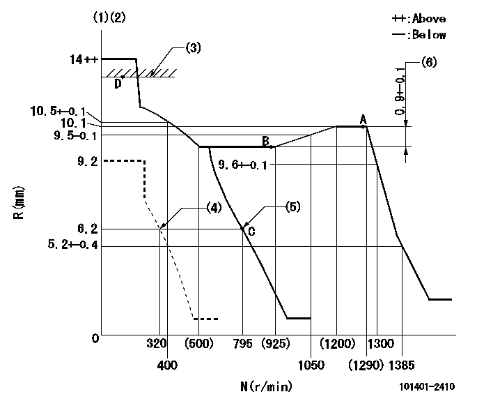
N:Pump speed
R:Rack position (mm)
(1)Target notch: K
(2)Tolerance for racks not indicated: +-0.05mm.
(3)RACK LIMIT
(4)Set idle sub-spring
(5)Main spring setting
(6)Rack difference between N = N1 and N = N2
----------
K=12 N1=1275r/min N2=900r/min
----------
----------
K=12 N1=1275r/min N2=900r/min
----------
Speed control lever angle
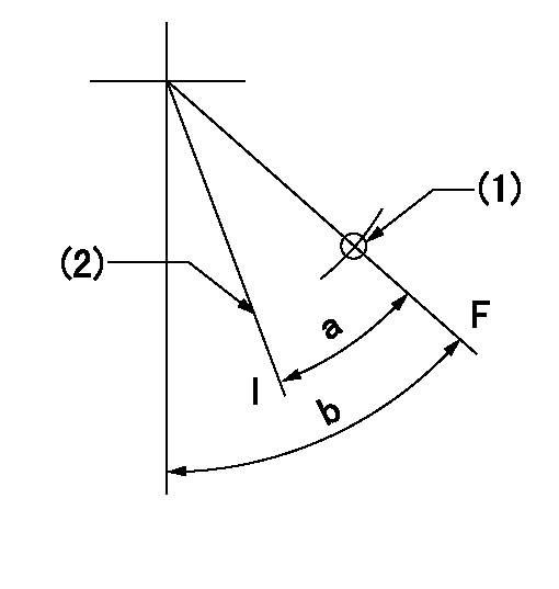
F:Full speed
I:Idle
(1)Use the hole at R = aa
(2)Stopper bolt setting
----------
aa=80mm
----------
a=(11deg)+-5deg b=(17deg)+-5deg
----------
aa=80mm
----------
a=(11deg)+-5deg b=(17deg)+-5deg
Stop lever angle
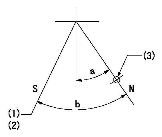
N:Pump normal
S:Stop the pump.
(1)Rack position aa or less, pump speed bb
(2)Normal stop
(3)Use the hole above R = cc
----------
aa=5.7mm bb=0r/min cc=25mm
----------
a=27deg+-5deg b=53deg+-5deg
----------
aa=5.7mm bb=0r/min cc=25mm
----------
a=27deg+-5deg b=53deg+-5deg
Timing setting

(1)Pump vertical direction
(2)Position of gear's standard threaded hole at No 1 cylinder's beginning of injection
(3)-
(4)-
----------
----------
a=(70deg)
----------
----------
a=(70deg)
Information:
Problem
The fuel injection pumps used on certain Remanufactured 1160 and 3208 Engines need to be inspected for gummy deposits.
Affected Product
Model & Identification Number
1160 (57V1-34485)
3208 (9WC1-1093), (5CD1-9736), (62W1-76455), (93Z1-10198)
Parts Stock Remanufactured Fuel Pump Part Numbers
This program applies only to pumps in parts stock with a date code prior to November, 1993 (UUDE). Date codes are in the MM/YY mode with the standard notation of NUMBERALKOD.
Parts Needed
Not applicable.
Action Required
Before installing or delivering any of the Affected Product, perform the following steps to ensure the internal fuel injection pump components are not stuck due to fuel pump gumming:
1. Remove the top cover of the fuel injection pump and check to ensure that all sleeves and levers are free and there are no gummy deposits on any of these components.2. If inspection performed in Step 1 indicates everything is clean, install top cover and return to parts stock.3. If inspection reveals components have gummy deposits, remove 12 ounces of fuel from the fuel pump housing and replace it with:-Fuel Injector Cleaner
or
-Carburetor/Choke Cleaner
4. Allow the components to soak in cleaning solution for 45 minutes. Then, rotate the engine crankshaft to rotate the fuel injection pump and check for free movement of the lever and sleeve (on pumps only, rotate the fuel pump camshaft). This will ensure the components have the gummy deposits removed.5. If the above procedures do not free the pump assembly, remove the individual pumps from the pump housing, clean them with cleaning solution, and install them back into the housing.6. If the engine or fuel pump will be used immediately, install the cover on the fuel injection pump, and install or deliver the engine or pump.7. If the engine or fuel pump will be returned to stock, DO NOT leave the fuel injection pump full of cleaning solution because it may not contain any rust inhibitors. Remove the cleaning solution, fill the fuel injector pump with clean diesel fuel, and install the cover on the pump.Service Claim Allowances
The inspection of the pump is a .5-hour job. If the pump needs to be cleaned, an additional .5 hour may be claimed. If the individual pumps need to be removed from the pump housing for cleaning, up to an additional 1.5 hours may be claimed.
US and Canadian Dealers Only - When submitting a claim for a fuel pump in Parts Stock, use 99Z00007 in the Product Identification Number Field.
Parts Disposition
Handle the parts in accordance with your Warranty Bulletin on warranty parts handling.