Information injection-pump assembly
BOSCH
9 400 612 405
9400612405
ZEXEL
101401-2400
1014012400
HINO
220402170A
220402170a
Rating:
Service parts 101401-2400 INJECTION-PUMP ASSEMBLY:
1.
_

6.
COUPLING PLATE
7.
COUPLING PLATE
8.
_
9.
_
11.
Nozzle and Holder
23600-3490A
12.
Open Pre:MPa(Kqf/cm2)
15.7{160}/21.6{220}
14.
NOZZLE
Cross reference number
BOSCH
9 400 612 405
9400612405
ZEXEL
101401-2400
1014012400
HINO
220402170A
220402170a
Zexel num
Bosch num
Firm num
Name
Calibration Data:
Adjustment conditions
Test oil
1404 Test oil ISO4113 or {SAEJ967d}
1404 Test oil ISO4113 or {SAEJ967d}
Test oil temperature
degC
40
40
45
Nozzle and nozzle holder
105780-8310
Nozzle
105780-0120
Bosch type code
1 688 901 990
Nozzle holder
105780-2240
Opening pressure
MPa
18
Opening pressure
kgf/cm2
184
Injection pipe
Outer diameter - inner diameter - length (mm) mm 6-2-600
Outer diameter - inner diameter - length (mm) mm 6-2-600
Overflow valve
131424-5720
Overflow valve opening pressure
kPa
255
221
289
Overflow valve opening pressure
kgf/cm2
2.6
2.25
2.95
Tester oil delivery pressure
kPa
255
255
255
Tester oil delivery pressure
kgf/cm2
2.6
2.6
2.6
Direction of rotation (viewed from drive side)
Right R
Right R
Injection timing adjustment
Direction of rotation (viewed from drive side)
Right R
Right R
Injection order
1-3-4-2
Pre-stroke
mm
4
3.97
4.03
Beginning of injection position
Drive side NO.1
Drive side NO.1
Difference between angles 1
Cal 1-3 deg. 90 89.75 90.25
Cal 1-3 deg. 90 89.75 90.25
Difference between angles 2
Cal 1-4 deg. 180 179.75 180.25
Cal 1-4 deg. 180 179.75 180.25
Difference between angles 3
Cyl.1-2 deg. 270 269.75 270.25
Cyl.1-2 deg. 270 269.75 270.25
Injection quantity adjustment
Adjusting point
-
Rack position
12.8
Pump speed
r/min
1000
1000
1000
Average injection quantity
mm3/st.
53.5
51.5
55.5
Max. variation between cylinders
%
0
-3
3
Basic
*
Fixing the rack
*
Injection quantity adjustment_02
Adjusting point
Z
Rack position
9.5+-0.5
Pump speed
r/min
375
375
375
Average injection quantity
mm3/st.
13
11.5
14.5
Max. variation between cylinders
%
0
-15
15
Fixing the rack
*
Injection quantity adjustment_03
Adjusting point
A
Rack position
R1(12.8)
Pump speed
r/min
1000
1000
1000
Average injection quantity
mm3/st.
53.5
52.5
54.5
Basic
*
Fixing the lever
*
Boost pressure
kPa
73.3
73.3
Boost pressure
mmHg
550
550
Injection quantity adjustment_04
Adjusting point
B
Rack position
R1+1.2
Pump speed
r/min
1600
1600
1600
Average injection quantity
mm3/st.
59
55
63
Fixing the lever
*
Boost pressure
kPa
73.3
73.3
Boost pressure
mmHg
550
550
Boost compensator adjustment
Pump speed
r/min
300
300
300
Rack position
R2-0.85
Boost pressure
kPa
42.7
41.4
44
Boost pressure
mmHg
320
310
330
Boost compensator adjustment_02
Pump speed
r/min
300
300
300
Rack position
R2(R1-0.
6)
Boost pressure
kPa
60
60
60
Boost pressure
mmHg
450
450
450
Timer adjustment
Pump speed
r/min
1350--
Advance angle
deg.
0
0
0
Remarks
Start
Start
Timer adjustment_02
Pump speed
r/min
1300
Advance angle
deg.
0.3
Timer adjustment_03
Pump speed
r/min
1600
Advance angle
deg.
2.5
2.2
2.8
Remarks
Finish
Finish
Test data Ex:
Governor adjustment
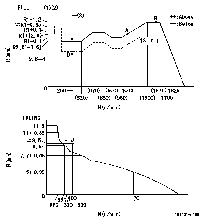
N:Pump speed
R:Rack position (mm)
(1)Torque cam stamping: T1
(2)Tolerance for racks not indicated: +-0.05mm.
(3)Boost compensator stroke: BCL
----------
T1=P27 BCL=0.85+-0.1mm
----------
----------
T1=P27 BCL=0.85+-0.1mm
----------
Speed control lever angle
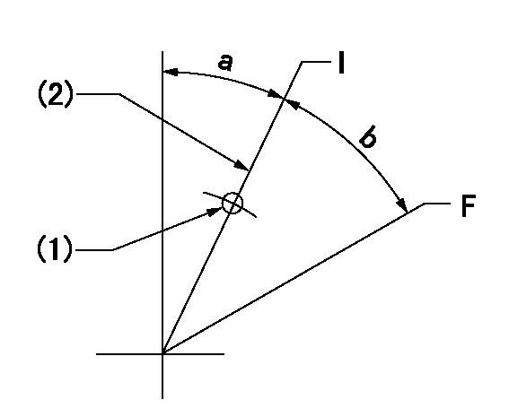
F:Full speed
I:Idle
(1)Use the hole at R = aa
(2)Stopper bolt set position 'H'
----------
aa=50mm
----------
a=22.5deg+-5deg b=40deg+-3deg
----------
aa=50mm
----------
a=22.5deg+-5deg b=40deg+-3deg
Stop lever angle
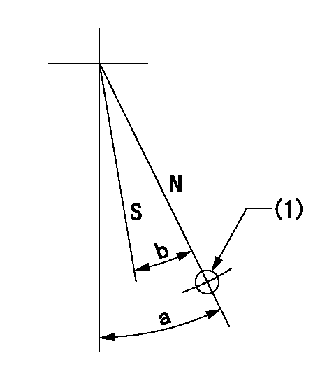
N:Pump normal
S:Stop the pump.
(1)Use the hole at R = aa
----------
aa=40mm
----------
a=40deg+-5deg b=40deg+-5deg
----------
aa=40mm
----------
a=40deg+-5deg b=40deg+-5deg
0000001501 AIR CYLINDER

(A): Speed lever
(B): Set bolt
(C): air cylinder
(D): nut
(E): fix
1. Air cylinder adjustment procedure
(1)With the speed lever in the idling position, temporarily set the clearance between speed lever (A) and set bolt (B) at approximately L1.
(2)Set the speed to N1 and supply positive pressure P1 to the air cylinder (C).
(3)Gradually push set bolt (B) out (approximately L2) and tighten nut (D) where the speed is N2 and the rack position is Ra.
(4)Apply positive pressure P1 several times.
(5)Confirm that the lever returns to the idle position at positive pressure P2.
(6)Also, confirm that the rack position is Rb at air pressure P1.
----------
L1=9mm L2=6.5mm Ra=10.65-0.2mm Rb=10.65-0.2mm N1=330r/min N2=330r/min P1=392+98kPa(4+1kgf/cm2) P2=0kPa(0kgf/cm2)
----------
----------
L1=9mm L2=6.5mm Ra=10.65-0.2mm Rb=10.65-0.2mm N1=330r/min N2=330r/min P1=392+98kPa(4+1kgf/cm2) P2=0kPa(0kgf/cm2)
----------
Timing setting

(1)Pump vertical direction
(2)Position of gear's standard threaded hole at No 1 cylinder's beginning of injection
(3)-
(4)-
----------
----------
a=(70deg)
----------
----------
a=(70deg)
Information:
The information supplied in this service letter may not be valid after the termination date of this program. Do not perform the work outlined in this Service Letter after the termination date without first contacting your Caterpillar product analyst.
This Program can be administered either before or after a failure. In either case the decision whether to apply the Program is made by the dealer. When reporting the repair, use "PS8088" as the Part Number and "7755" as the Group Number. If administered before failure, use "56" as the Warranty Claim Description Code and use "T" as the SIMS Description Code. If administered after failure, use "96" as the Warranty Claim Description Code and use "Z" as the SIMS Description Code.
This Revised Service Letter replaces the January 25, 1994 (Revised December 1994) Service Letter. Changes have been made to the Parts Stock Action.
Termination Date
January 31, 1996Problem
The fuel nozzles used on certain 3208 Engines may crack at the braze joint.
Affected Product
Model & Identification Number
3208 ( 30A5540-5956 (Arrangements 9Y8574, 9Y8575, 1228675, 1228676, 1228679, 1228680); 62W74820-80012 (Arrangements 0R0776, 0R0975, 0R0976, 0R2818, 0R2819, 0R2875, 0R3231); 5YF1531-2058 (Arrangements 4P2649, 4P3027, 9Y2229, 9Y3136, 1042666, 1061496, 1077956, 1077957); 01Z26425-28100 (Arrangements 2W1320, 2W1325, 7W7500, 7W9150, 1013714, 1176582); 03Z11912-13004 (Arrangements 4P1724, 1067075, 1108885, 1168163, 1168164, 1168165, 1214692); 51Z81870-82239 (Arrangements 4P0921, 4P0922, 111364); 93Z8798-11332 (Arrangement 0R1098); 99R1533-1541 (Arrangement 5R6639); 79V24858 (Arrangement 1W0331))
Parts Needed
1 - 0R2503 Nozzle Assembly (Reman Equivalent of 1W5829)*1 - 0R2821 Nozzle Assembly (Reman Equivalent of 7W3710)*1 - 0R3284 Nozzle Assembly (Reman Equivalent of 4W8483)*1 - 1153354 Nozzle Assembly (No Reman Equivalent)**Use as requiredAction Required
Parts Stock
Remove all 0R2503, 0R2821, 0R3284, 1W5829, 4W8483, 7W3710, and 1153354 Nozzle Assemblies from Parts Stock with date codes of D--3, E--3, F--3, G--3, H--3, J--3, K--3, L--3, M--3, A--4, B--4, C--4, D--4, E--4, or F--4. Date codes are located on the nozzle assembly as shown below:
Location of Date CodeAffected Product
Remove all 0R2503, 0R2821, 0R3284, 1W5829, 4W8483, 7W3710, and 1153354 Nozzle Assemblies with date codes of D--3, E--3, F--3, G--3, H--3, J--3, K--3, L--3, M--3, A--4, B--4, C--4, D--4, E--4, or F--4 from the engine and replace with new nozzle assemblies or the remanufactured equivalent nozzle assemblies.
Service Claim Allowances
Parts Stock
US and Canadian Dealers Only - When submitting a Parts Stock claim use 99Z00007 in the Product Identification Number Field.
Affected Product
Industrial and Marine Engines Up to 6-hours labor may be claimed.
Truck Engines Claim labor hours in accordance with TRG book.
Parts Disposition
U.S. and Canadian Dealers
Return all 0R2503, 0R2821, 0R3284, 1W5829, 4W8483, 7W3710, and 1153354 Nozzle Assemblies that are removed from Parts Stock and a copy of the claim to:
Caterpillar Inc.
Attn:Howard Jenkel
Service Claims Room
8201 N. University
Peoria, IL 61615
For remanufactured nozzle assemblies 0R2503, 0R2821, and 0R3284, include a copy of the "Core Credit Request Packing List".
All Other Dealers
Handle the parts in accordance with your Warranty Bulletin on warranty parts handling.