Information injection-pump assembly
ZEXEL
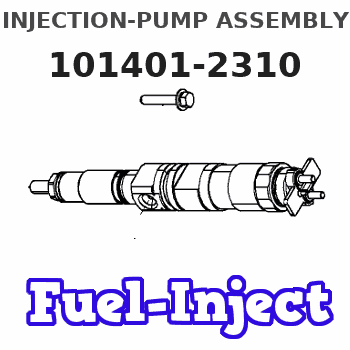
101401-2310
1014012310
Rating:
Service parts 101401-2310 INJECTION-PUMP ASSEMBLY:
1.
_
6.
COUPLING PLATE
7.
COUPLING PLATE
8.
_
9.
_
11.
Nozzle and Holder
23600-2601A
12.
Open Pre:MPa(Kqf/cm2)
21.6{220}
15.
NOZZLE SET
Cross reference number
ZEXEL
101401-2310
1014012310
Zexel num
Bosch num
Firm num
Name
101401-2310
INJECTION-PUMP ASSEMBLY
14BC PE4A,5A, PE
14BC PE4A,5A, PE
Calibration Data:
Adjustment conditions
Test oil
1404 Test oil ISO4113 or {SAEJ967d}
1404 Test oil ISO4113 or {SAEJ967d}
Test oil temperature
degC
40
40
45
Nozzle and nozzle holder
105780-8140
Bosch type code
EF8511/9A
Nozzle
105780-0000
Bosch type code
DN12SD12T
Nozzle holder
105780-2080
Bosch type code
EF8511/9
Opening pressure
MPa
17.2
Opening pressure
kgf/cm2
175
Injection pipe
Outer diameter - inner diameter - length (mm) mm 6-2-600
Outer diameter - inner diameter - length (mm) mm 6-2-600
Overflow valve
134424-0920
Overflow valve opening pressure
kPa
162
147
177
Overflow valve opening pressure
kgf/cm2
1.65
1.5
1.8
Tester oil delivery pressure
kPa
157
157
157
Tester oil delivery pressure
kgf/cm2
1.6
1.6
1.6
Direction of rotation (viewed from drive side)
Right R
Right R
Injection timing adjustment
Direction of rotation (viewed from drive side)
Right R
Right R
Injection order
1-3-4-2
Pre-stroke
mm
3.2
3.17
3.23
Beginning of injection position
Drive side NO.1
Drive side NO.1
Difference between angles 1
Cal 1-3 deg. 90 89.75 90.25
Cal 1-3 deg. 90 89.75 90.25
Difference between angles 2
Cal 1-4 deg. 180 179.75 180.25
Cal 1-4 deg. 180 179.75 180.25
Difference between angles 3
Cyl.1-2 deg. 270 269.75 270.25
Cyl.1-2 deg. 270 269.75 270.25
Injection quantity adjustment
Adjusting point
A
Rack position
12.8
Pump speed
r/min
1500
1500
1500
Average injection quantity
mm3/st.
115
113
117
Max. variation between cylinders
%
0
-3
3
Basic
*
Fixing the lever
*
Boost pressure
kPa
78.6
78.6
Boost pressure
mmHg
590
590
Injection quantity adjustment_02
Adjusting point
C
Rack position
9+-0.5
Pump speed
r/min
405
405
405
Average injection quantity
mm3/st.
9
7.5
10.5
Max. variation between cylinders
%
0
-15
15
Fixing the rack
*
Boost pressure
kPa
0
0
0
Boost pressure
mmHg
0
0
0
Boost compensator adjustment
Pump speed
r/min
900
900
900
Rack position
R1-1.85
Boost pressure
kPa
16
13.3
18.7
Boost pressure
mmHg
120
100
140
Boost compensator adjustment_02
Pump speed
r/min
900
900
900
Rack position
R1(12.8)
Boost pressure
kPa
65.3
58.6
72
Boost pressure
mmHg
490
440
540
Timer adjustment
Pump speed
r/min
1275--
Advance angle
deg.
0
0
0
Load
1/4
Remarks
Start
Start
Timer adjustment_02
Pump speed
r/min
1225
Advance angle
deg.
0.3
Load
1/4
Timer adjustment_03
Pump speed
r/min
1450
Advance angle
deg.
3.25
2.95
3.55
Load
4/4
Remarks
Finish
Finish
Test data Ex:
Governor adjustment
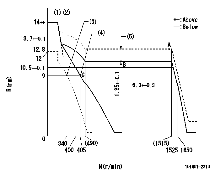
N:Pump speed
R:Rack position (mm)
(1)Target notch: K
(2)Tolerances for racks not indicated: +-0.05mm.
(3)Set idle sub-spring
(4)Main spring setting
(5)Boost compensator stroke
----------
K=10
----------
----------
K=10
----------
Speed control lever angle
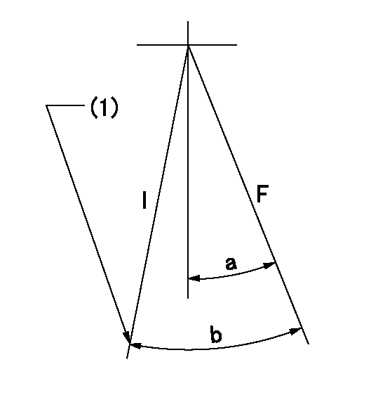
F:Full speed
I:Idle
(1)Stopper bolt setting
----------
----------
a=10deg+-5deg b=26deg+-5deg
----------
----------
a=10deg+-5deg b=26deg+-5deg
Stop lever angle

N:Pump normal
S:Stop the pump.
(1)Pump speed aa and rack position bb (to be sealed at delivery)
----------
aa=0r/min bb=1-0.2mm
----------
a=21deg+-5deg b=(55deg)
----------
aa=0r/min bb=1-0.2mm
----------
a=21deg+-5deg b=(55deg)
Timing setting

(1)Pump vertical direction
(2)Position of gear's standard threaded hole at No 1 cylinder's beginning of injection
(3)-
(4)-
----------
----------
a=(70deg)
----------
----------
a=(70deg)
Information:
Cooling System
Never add coolant to an overheated engine; allow the engine to cool first.Check the specific gravity of the antifreeze coolant solution frequently in cold weather to ensure adequate protection.If the machine is to be stored in, or shipped to, an area with below freezing temperatures; the cooling system must be protected against freezing to the lowest expected outside temperature.All water is corrosive at engine operating temperature. The cooling system should be protected with conditioner at all times regardless of the concentration of antifreeze. This can be done by using Caterpillar coolant conditioner elements. Use a precharge element when filling the system or changing coolant. Install a new maintenance element every 250 service hours during operation.Do not use Caterpillar coolant conditioner elements with Dowtherm 209 Full-Fill coolant. Follow the instructions provided with the Dowtherm 209 Full-Fill coolant.
Coolant should be drained and replaced every 2000 service hours or 1 year. However, when coolant conditioner maintenance elements are replaced every 250 service hours as recommended, the drain period can be extended to 4000 service hours or 2 years. If your engine does not use coolant conditioner elements, see "Cooling System" under "Maintenance Recommendations" in your Maintenance (Lubrication and Maintenance) Guide.Premix antifreeze coolant solution to provide protection to the lowest expected outside temperature. Pure undiluted antifreeze will freeze at -23°C (-10°F).Use clean water that is low in scale forming mineral. Do not use softened water.Filling at over 20 liters (5 U.S. gallons) per minute can cause air pockets in the cooling system.After draining and refilling the cooling system, start and operate the engine with the fill cap off until the coolant level stabilizes. Add coolant as necessary to fill the system.When the engine is shipped from the factory, its cooling system is protected to -28°C (-20°F), with permanent-type antifreeze.Operate with a thermostat in the cooling system year-round. Overheating can arise without a thermostat.Fuel System
Fill the fuel tank at the end of each day of operation to drive out moist air and to prevent condensation. Do not fill the tank to the top. The fuel expands as it gets warm and may overflow.
Do not fill the fuel filters with fuel before installing them. Contaminated fuel will cause accelerated wear to the fuel system parts.
Check the fuel level with the dipstick in the filler opening. Drain the water and sediment from the fuel tank at the start of a shift or after the fuel tank has been filled and allowed to stand for 5 to 10 minutes.After changing the fuel filters, always bleed the fuel system to remove air bubbles from the system.Drain water and sediment from any fuel storage tank weekly, and before the tank is refilled. This will help prevent water or sediment from being pumped from the storage tank into the machine fuel tank.Use only fuel as recommended in the 'Fuel, Coolant and Lubricant" section of this Guide.
Have questions with 101401-2310?
Group cross 101401-2310 ZEXEL
101401-2310
INJECTION-PUMP ASSEMBLY