Information injection-pump assembly
BOSCH
9 400 613 183
9400613183
ZEXEL
101401-2302
1014012302
HINO
220204251C
220204251c
Rating:
Service parts 101401-2302 INJECTION-PUMP ASSEMBLY:
1.
_
6.
COUPLING PLATE
7.
COUPLING PLATE
8.
_
9.
_
11.
Nozzle and Holder
23600-2601A
12.
Open Pre:MPa(Kqf/cm2)
21.6{220}
15.
NOZZLE SET
Cross reference number
BOSCH
9 400 613 183
9400613183
ZEXEL
101401-2302
1014012302
HINO
220204251C
220204251c
Zexel num
Bosch num
Firm num
Name
101401-2302
9 400 613 183
220204251C HINO
INJECTION-PUMP ASSEMBLY
W04C-T K 14BC INJECTION PUMP ASSY PE4A,5A, PE
W04C-T K 14BC INJECTION PUMP ASSY PE4A,5A, PE
Calibration Data:
Adjustment conditions
Test oil
1404 Test oil ISO4113 or {SAEJ967d}
1404 Test oil ISO4113 or {SAEJ967d}
Test oil temperature
degC
40
40
45
Nozzle and nozzle holder
105780-8140
Bosch type code
EF8511/9A
Nozzle
105780-0000
Bosch type code
DN12SD12T
Nozzle holder
105780-2080
Bosch type code
EF8511/9
Opening pressure
MPa
17.2
Opening pressure
kgf/cm2
175
Injection pipe
Outer diameter - inner diameter - length (mm) mm 6-2-600
Outer diameter - inner diameter - length (mm) mm 6-2-600
Overflow valve
134424-0920
Overflow valve opening pressure
kPa
162
147
177
Overflow valve opening pressure
kgf/cm2
1.65
1.5
1.8
Tester oil delivery pressure
kPa
157
157
157
Tester oil delivery pressure
kgf/cm2
1.6
1.6
1.6
Direction of rotation (viewed from drive side)
Right R
Right R
Injection timing adjustment
Direction of rotation (viewed from drive side)
Right R
Right R
Injection order
1-3-4-2
Pre-stroke
mm
3.2
3.17
3.23
Beginning of injection position
Drive side NO.1
Drive side NO.1
Difference between angles 1
Cal 1-3 deg. 90 89.75 90.25
Cal 1-3 deg. 90 89.75 90.25
Difference between angles 2
Cal 1-4 deg. 180 179.75 180.25
Cal 1-4 deg. 180 179.75 180.25
Difference between angles 3
Cyl.1-2 deg. 270 269.75 270.25
Cyl.1-2 deg. 270 269.75 270.25
Injection quantity adjustment
Adjusting point
A
Rack position
11
Pump speed
r/min
1500
1500
1500
Average injection quantity
mm3/st.
95.5
93.5
97.5
Max. variation between cylinders
%
0
-3
3
Basic
*
Fixing the lever
*
Boost pressure
kPa
84
84
Boost pressure
mmHg
630
630
Injection quantity adjustment_02
Adjusting point
B
Rack position
R1-0.95
Pump speed
r/min
900
900
900
Average injection quantity
mm3/st.
73
67
79
Fixing the lever
*
Boost pressure
kPa
0
0
0
Boost pressure
mmHg
0
0
0
Injection quantity adjustment_03
Adjusting point
C
Rack position
8.2+-0.5
Pump speed
r/min
400
400
400
Average injection quantity
mm3/st.
8.5
7
10
Max. variation between cylinders
%
0
-15
15
Fixing the rack
*
Boost pressure
kPa
0
0
0
Boost pressure
mmHg
0
0
0
Boost compensator adjustment
Pump speed
r/min
900
900
900
Rack position
R1-0.95
Boost pressure
kPa
26.7
24
29.4
Boost pressure
mmHg
200
180
220
Boost compensator adjustment_02
Pump speed
r/min
900
900
900
Rack position
R1(11)
Boost pressure
kPa
70.6
63.9
77.3
Boost pressure
mmHg
530
480
580
Timer adjustment
Pump speed
r/min
1275--
Advance angle
deg.
0
0
0
Load
1/4
Remarks
Start
Start
Timer adjustment_02
Pump speed
r/min
1225
Advance angle
deg.
0.3
Load
1/4
Timer adjustment_03
Pump speed
r/min
1450
Advance angle
deg.
3.25
2.95
3.55
Load
4/4
Remarks
Finish
Finish
Test data Ex:
Governor adjustment
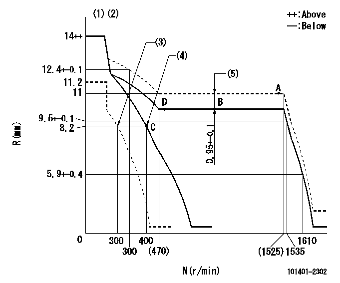
N:Pump speed
R:Rack position (mm)
(1)Target notch: K
(2)Tolerance for racks not indicated: +-0.05mm.
(3)Set idle sub-spring
(4)Main spring setting
(5)Boost compensator stroke (at N = N1)
----------
K=6 N1=900r/min
----------
----------
K=6 N1=900r/min
----------
Speed control lever angle
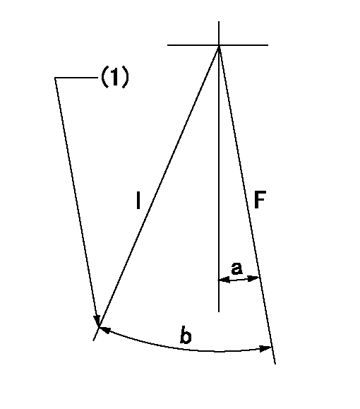
F:Full speed
I:Idle
(1)Stopper bolt setting
----------
----------
a=9deg+-5deg b=25deg+-5deg
----------
----------
a=9deg+-5deg b=25deg+-5deg
Stop lever angle

N:Pump normal
S:Stop the pump.
(1)Pump speed aa and rack position bb (to be sealed at delivery)
(2)Normal
----------
aa=0r/min bb=1-0.2mm
----------
a=21deg+-5deg b=(55deg)
----------
aa=0r/min bb=1-0.2mm
----------
a=21deg+-5deg b=(55deg)
Timing setting

(1)Pump vertical direction
(2)Position of gear's standard threaded hole at No 1 cylinder's beginning of injection
(3)-
(4)-
----------
----------
a=(70deg)
----------
----------
a=(70deg)
Information:
9. If the engine oil pressure gauge does not register within 10 seconds, stop the engine by pulling up on the accelerator pedal. Have corrections made.10. Keep the engine at low idle until the systems are warm.11. Watch all gauges and indicators. They must have correct readings before moving the machine.Below 0°C (32°F)
1. Follow the steps under "Above 0°C (32°F)."
If the engine does not start after two attempts, use starting fluid. This will prevent excessive battery drain and starting motor overheating.Use starting fluid (ether) only while cranking the engine.Use sparingly, excessive ether can cause piston and ring damage.Ether is to be used for cold weather starting purposes only.
Keep batteries charged to a corrected specific gravity of 1.250 or above. Otherwise, an external electrical source may be required. 2. Use starting fluid while cranking the engine. Push the button located below the start switch, at two second intervals only. A metered amount of starting fluid (ether) is released each time the button is pushed.3. Use additional starting fluid every two seconds until the engine starts.4. Release the start switch when the engine starts. Continue to inject ether until the engine runs smoothly.For starting below - 18°C (0°F), use additional starting aids. A coolant
Have questions with 101401-2302?
Group cross 101401-2302 ZEXEL
Hino
101401-2302
9 400 613 183
220204251C
INJECTION-PUMP ASSEMBLY
W04C-T
W04C-T