Information injection-pump assembly
BOSCH
F 019 Z10 308
f019z10308
ZEXEL
101401-2301
1014012301
HINO
220204251B
220204251b
Rating:
Service parts 101401-2301 INJECTION-PUMP ASSEMBLY:
1.
_
6.
COUPLING PLATE
7.
COUPLING PLATE
8.
_
9.
_
11.
Nozzle and Holder
23600-2601A
12.
Open Pre:MPa(Kqf/cm2)
21.6{220}
15.
NOZZLE SET
Cross reference number
BOSCH
F 019 Z10 308
f019z10308
ZEXEL
101401-2301
1014012301
HINO
220204251B
220204251b
Zexel num
Bosch num
Firm num
Name
F 019 Z10 308
220204251B HINO
INJECTION-PUMP ASSEMBLY
W04C-T A * K 14BC PE4A,5A, PE
W04C-T A * K 14BC PE4A,5A, PE
Calibration Data:
Adjustment conditions
Test oil
1404 Test oil ISO4113 or {SAEJ967d}
1404 Test oil ISO4113 or {SAEJ967d}
Test oil temperature
degC
40
40
45
Nozzle and nozzle holder
105780-8140
Bosch type code
EF8511/9A
Nozzle
105780-0000
Bosch type code
DN12SD12T
Nozzle holder
105780-2080
Bosch type code
EF8511/9
Opening pressure
MPa
17.2
Opening pressure
kgf/cm2
175
Injection pipe
Outer diameter - inner diameter - length (mm) mm 6-2-600
Outer diameter - inner diameter - length (mm) mm 6-2-600
Overflow valve
134424-0920
Overflow valve opening pressure
kPa
162
147
177
Overflow valve opening pressure
kgf/cm2
1.65
1.5
1.8
Tester oil delivery pressure
kPa
157
157
157
Tester oil delivery pressure
kgf/cm2
1.6
1.6
1.6
Direction of rotation (viewed from drive side)
Right R
Right R
Injection timing adjustment
Direction of rotation (viewed from drive side)
Right R
Right R
Injection order
1-3-4-2
Pre-stroke
mm
3.2
3.17
3.23
Beginning of injection position
Drive side NO.1
Drive side NO.1
Difference between angles 1
Cal 1-3 deg. 90 89.75 90.25
Cal 1-3 deg. 90 89.75 90.25
Difference between angles 2
Cal 1-4 deg. 180 179.75 180.25
Cal 1-4 deg. 180 179.75 180.25
Difference between angles 3
Cyl.1-2 deg. 270 269.75 270.25
Cyl.1-2 deg. 270 269.75 270.25
Injection quantity adjustment
Adjusting point
A
Rack position
11
Pump speed
r/min
1500
1500
1500
Average injection quantity
mm3/st.
95.5
93.5
97.5
Max. variation between cylinders
%
0
-3
3
Basic
*
Fixing the lever
*
Boost pressure
kPa
84
84
Boost pressure
mmHg
630
630
Injection quantity adjustment_02
Adjusting point
B
Rack position
R1-0.95
Pump speed
r/min
900
900
900
Average injection quantity
mm3/st.
73
67
79
Fixing the lever
*
Boost pressure
kPa
0
0
0
Boost pressure
mmHg
0
0
0
Injection quantity adjustment_03
Adjusting point
C
Rack position
8.2+-0.5
Pump speed
r/min
400
400
400
Average injection quantity
mm3/st.
8.5
7
10
Max. variation between cylinders
%
0
-15
15
Fixing the rack
*
Boost pressure
kPa
0
0
0
Boost pressure
mmHg
0
0
0
Boost compensator adjustment
Pump speed
r/min
900
900
900
Rack position
R1-0.95
Boost pressure
kPa
26.7
24
29.4
Boost pressure
mmHg
200
180
220
Boost compensator adjustment_02
Pump speed
r/min
900
900
900
Rack position
R1(11)
Boost pressure
kPa
70.6
63.9
77.3
Boost pressure
mmHg
530
480
580
Timer adjustment
Pump speed
r/min
1275--
Advance angle
deg.
0
0
0
Load
1/4
Remarks
Start
Start
Timer adjustment_02
Pump speed
r/min
1225
Advance angle
deg.
0.3
Load
1/4
Timer adjustment_03
Pump speed
r/min
1450
Advance angle
deg.
3.25
2.95
3.55
Load
4/4
Remarks
Finish
Finish
Test data Ex:
Governor adjustment
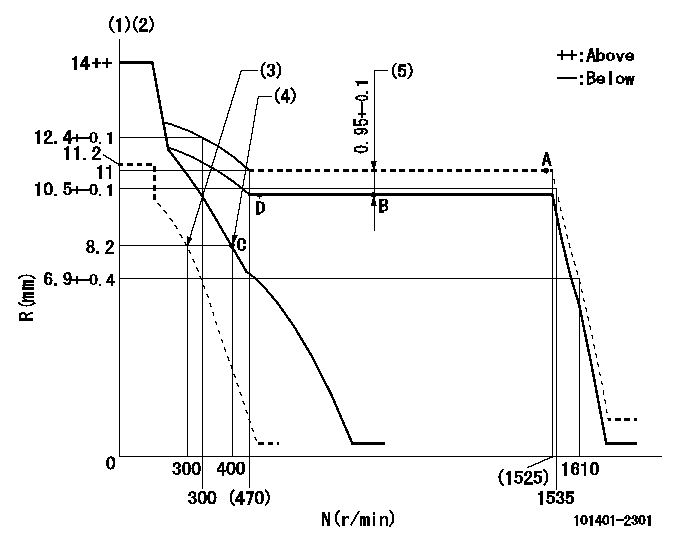
N:Pump speed
R:Rack position (mm)
(1)Target notch: K
(2)Tolerance for racks not indicated: +-0.05mm.
(3)Set idle sub-spring
(4)Main spring setting
(5)Boost compensator stroke (at N = N1)
----------
K=6 N1=900r/min
----------
----------
K=6 N1=900r/min
----------
Speed control lever angle
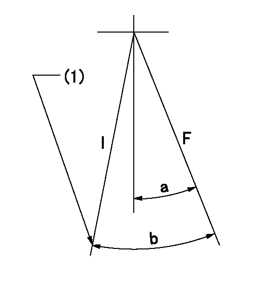
F:Full speed
I:Idle
(1)Stopper bolt setting
----------
----------
a=9deg+-5deg b=25deg+-5deg
----------
----------
a=9deg+-5deg b=25deg+-5deg
Stop lever angle

N:Pump normal
S:Stop the pump.
(1)Pump speed aa and rack position bb (to be sealed at delivery)
----------
aa=0r/min bb=1-0.2mm
----------
a=21deg+-5deg b=(55deg)
----------
aa=0r/min bb=1-0.2mm
----------
a=21deg+-5deg b=(55deg)
Timing setting

(1)Pump vertical direction
(2)Position of gear's standard threaded hole at No 1 cylinder's beginning of injection
(3)-
(4)-
----------
----------
a=(70deg)
----------
----------
a=(70deg)
Information:
Coolant Conditioner Elements
At operating temperature, the engine coolant is hot and under pressure.Steam can cause personal injury.Check the coolant level ONLY when the engine is stopped and the radiator fill cap is cool enough to touch with your hand.Remove the fill cap slowly to relieve pressure.Cooling System Conditioner contains alkali. Avoid contact with skin and eyes to prevent personal injury.
All water is corrosive at engine operating temperature. Use Caterpillar Coolant Conditioner Elements to treat either plain water or ethylene glycol solution.Do not use Caterpillar Coolant Conditioner Elements if Dowtherm 209 Full-Fill Coolant is used. Follow the recommendations with the Dowtherm 209 Full-Fill Coolant.
Use a Caterpillar Part Number 1W5518 precharge element when the cooling system is drained and refilled. This will establish the proper initial conditioner concentration.Use a Caterpillar Part Number 9N6123 maintenance element every 250 service hours thereafter, to maintain the proper conditioner concentration.If the coolant conditioner elements have been regularly changed at 250 service hours, the change period for engine coolant can be extended to 4000 hours.Refer to the "Maintenance" (Lubrication and Maintenance) Guide for the procedures to change the antifreeze solution, or flush the cooling system.To Change Element
1. Remove the radiator cap slowly to relieve pressure in the cooling system. 2. Close the inlet valve and the outlet valve at the element base. Turn each handle clockwise to close each valve. 3. Remove the coolant conditioner element. Discard the element. 4. Clean the element mounting base. Make certain all of the old element gasket material is removed.5. Use the correct precharge or maintenance element for your cooling system. Elements are sized according to the cooling system capacity. 6. Coat the seal of the element with a thin film of clean engine oil or antifreeze. 7. Install the element. Tighten it until the seal contacts the base, then tighten it an additional 3/4 turn. 8. Open the inlet valve and the outlet valve. 9. Maintain the coolant level above the low level plate.10. Clean and install the radiator cap.11. Start the engine and check for leaks.Fuel Specifications for Direct Injection Engines
Caterpillar Diesel Engines have the ability to burn a wide variety of fuels. These fuels are divided into two general groups, preferred and permissible.Types of Fuel
The preferred fuels provide maximum engine service life and performance. They are distillate fuels. They are commonly called fuel oil, furnace oil, diesel fuel, gas oil, or kerosene.The permissible fuels are crude oils or blended fuels. Use of these fuels can result in higher maintenance costs and reduced engine service life.See Caterpillar Form Number SEHS7067, "Fuels for Caterpillar Diesel Engines," for a detailed summary of preferred and permissible fuels and their specifications.Cetane Requirement
The minimum cetane number recommended for the engine is 40.Fuel Cloud Point
Fuel waxing can plug the fuel filters in cold weather. The fuel cloud point must be below the temperature of the surrounding air to prevent filter waxing and power loss. Fuel heating attachments are available from your Caterpillar dealer to minimize fuel filter waxing.Fuel Sulfur Content
The percent of sulfur