Information injection-pump assembly
BOSCH
9 400 613 660
9400613660
ZEXEL
101401-2282
1014012282
HINO
220203961A
220203961a
Rating:
Service parts 101401-2282 INJECTION-PUMP ASSEMBLY:
1.
_
6.
COUPLING PLATE
7.
COUPLING PLATE
8.
_
9.
_
11.
Nozzle and Holder
12.
Open Pre:MPa(Kqf/cm2)
21.6(220)
15.
NOZZLE SET
Cross reference number
BOSCH
9 400 613 660
9400613660
ZEXEL
101401-2282
1014012282
HINO
220203961A
220203961a
Zexel num
Bosch num
Firm num
Name
101401-2282
9 400 613 660
220203961A HINO
INJECTION-PUMP ASSEMBLY
W04C-T * K
W04C-T * K
Calibration Data:
Adjustment conditions
Test oil
1404 Test oil ISO4113 or {SAEJ967d}
1404 Test oil ISO4113 or {SAEJ967d}
Test oil temperature
degC
40
40
45
Nozzle and nozzle holder
105780-8140
Bosch type code
EF8511/9A
Nozzle
105780-0000
Bosch type code
DN12SD12T
Nozzle holder
105780-2080
Bosch type code
EF8511/9
Opening pressure
MPa
17.2
Opening pressure
kgf/cm2
175
Injection pipe
Outer diameter - inner diameter - length (mm) mm 6-2-600
Outer diameter - inner diameter - length (mm) mm 6-2-600
Overflow valve
134424-0920
Overflow valve opening pressure
kPa
162
147
177
Overflow valve opening pressure
kgf/cm2
1.65
1.5
1.8
Tester oil delivery pressure
kPa
157
157
157
Tester oil delivery pressure
kgf/cm2
1.6
1.6
1.6
Direction of rotation (viewed from drive side)
Right R
Right R
Injection timing adjustment
Direction of rotation (viewed from drive side)
Right R
Right R
Injection order
1-3-4-2
Pre-stroke
mm
3.2
3.17
3.23
Beginning of injection position
Drive side NO.1
Drive side NO.1
Difference between angles 1
Cal 1-3 deg. 90 89.75 90.25
Cal 1-3 deg. 90 89.75 90.25
Difference between angles 2
Cal 1-4 deg. 180 179.75 180.25
Cal 1-4 deg. 180 179.75 180.25
Difference between angles 3
Cyl.1-2 deg. 270 269.75 270.25
Cyl.1-2 deg. 270 269.75 270.25
Injection quantity adjustment
Adjusting point
A
Rack position
10.8
Pump speed
r/min
900
900
900
Average injection quantity
mm3/st.
88.2
86.2
90.2
Max. variation between cylinders
%
0
-3
3
Basic
*
Fixing the lever
*
Boost pressure
kPa
48
48
Boost pressure
mmHg
360
360
Injection quantity adjustment_02
Adjusting point
C
Rack position
7.9+-0.5
Pump speed
r/min
390
390
390
Average injection quantity
mm3/st.
8.4
6.9
9.9
Max. variation between cylinders
%
0
-15
15
Fixing the rack
*
Boost pressure
kPa
0
0
0
Boost pressure
mmHg
0
0
0
Boost compensator adjustment
Pump speed
r/min
650
650
650
Rack position
R1-0.75
Boost pressure
kPa
21.3
18.6
24
Boost pressure
mmHg
160
140
180
Boost compensator adjustment_02
Pump speed
r/min
650
650
650
Rack position
R1(10.8)
Boost pressure
kPa
34.7
34.7
34.7
Boost pressure
mmHg
260
260
260
Timer adjustment
Pump speed
r/min
1350--
Advance angle
deg.
0
0
0
Remarks
Start
Start
Timer adjustment_02
Pump speed
r/min
1300
Advance angle
deg.
0.3
Timer adjustment_03
Pump speed
r/min
1500
Advance angle
deg.
2.5
2
3
Timer adjustment_04
Pump speed
r/min
-
Advance angle
deg.
3.5
3.5
3.5
Remarks
Measure the actual speed, stop
Measure the actual speed, stop
Test data Ex:
Governor adjustment
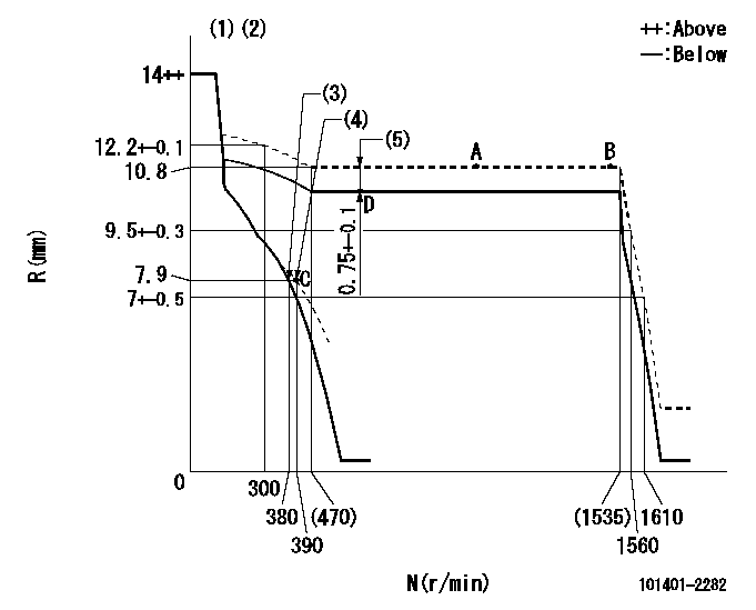
N:Pump speed
R:Rack position (mm)
(1)Target notch: K
(2)Tolerance for racks not indicated: +-0.05mm.
(3)Main spring setting
(4)Set idle sub-spring
(5)Boost compensator stroke (at N = N1)
----------
K=10 N1=650r/min
----------
----------
K=10 N1=650r/min
----------
Speed control lever angle
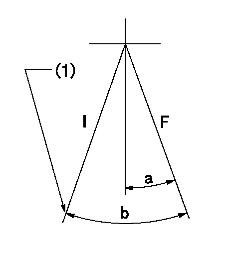
F:Full speed
I:Idle
(1)Stopper bolt setting
----------
----------
a=(12deg)+-5deg b=(26deg)+-5deg
----------
----------
a=(12deg)+-5deg b=(26deg)+-5deg
Stop lever angle

N:Pump normal
S:Stop the pump.
(1)Pump speed aa and rack position bb (to be sealed at delivery)
(2)Normal
----------
aa=0r/min bb=1-0.2mm
----------
a=21deg+-5deg b=(55deg)
----------
aa=0r/min bb=1-0.2mm
----------
a=21deg+-5deg b=(55deg)
Timing setting

(1)Pump vertical direction
(2)Position of gear's standard threaded hole at No 1 cylinder's beginning of injection
(3)-
(4)-
----------
----------
a=(70deg)
----------
----------
a=(70deg)
Information:
start by:a) remove fuel injection pump housing and governor 1. Install the fuel injection pump housing on tool (A).2. Remove the bolts (1) that hold the governor housing (2) to the fuel injection pump housing.3. Remove the governor housing (2). 4. Remove two springs (4) and the seat (5) from the governor housing.5. Remove the seat (7) from the shaft.6. Remove the spring (6) from the shaft.7. Remove the cover (3) from the pump housing. 8. Remove the shaft (8) and the lever (9) from the pump housing. 9. Remove the thrust collar (11) from the shaft.10. Remove the cover (10) from the pump housing. 11. Loosen the two bolts (13) that hold the torque spring assembly (12) and remove it from the pump housing. 12. Remove the pin (15) from the pump housing.13. Remove the screw (14) and the nut (16) from the pump housing.14. Remove the ring that holds the lever and remove the lever (18) from the dowel (17).15. Remove the dowel (17) from the pump housing. Dowel does not need to be removed unless camshaft is to be removed.
Pull on the shield only a small amount in each location so it will not have distortion or damage. A damaged shield must be replaced.
16. Remove the shield (19) from the camshaft with tool (B). 17. Install the timing pin (C) to hold the camshaft.18. Remove the bolts (20) that hold the flyweight assembly to the camshaft. 19. Remove the flyweight assembly (21) from the camshaft.20. Remove the timing pin (C) from the pump housing.Connection Of Governor To Fuel Injection Pump Housing
1. Put the fuel injection pump housing on the bracket assembly (A).2. Install the timing pin (B) to hold the camshaft.3. Put the flyweight assembly (1) in position on the camshaft. Be sure the pin that holds the shaft (2) is in position on the back of the flyweight assembly.4. Install the bolts that hold the flyweight assembly to the camshaft and tighten to a torque of 10 2 lb. ft. (1.38 0.28 mkg).5. Remove the timing pin (B). 6. Put the shield (3) in position over the flyweights. 7. Use the driver (C) to install the shield the remainder of the way on to the camshaft. 8. Put a new O-ring seal on the dowel (4) and install the dowel in the pump housing. Make the dowel even with the machined surface of the counterbore on the outside of the housing. 9. Put the lever (8) on the dowel (4) and install the ring that holds it on the dowel.10. Install the screw (6) and the nut (7) in the pump housing.11. Install the pin (5) in the pump housing. 12. Put the torque spring assembly (10) in position on the housing and tighten the two bolts (11) that hold it to the housing.13. Install the cover (9) on the pump housing. 14. Put the thrust collar (13) in position between the flyweights. Lift the flyweights up with a piece of wire
Have questions with 101401-2282?
Group cross 101401-2282 ZEXEL
Hino
Hino
Hino
Hino
Hino
Hino
Hino
Hino
101401-2282
9 400 613 660
220203961A
INJECTION-PUMP ASSEMBLY
W04C-T
W04C-T