Information injection-pump assembly
ZEXEL
101401-2281
1014012281
Rating:
Service parts 101401-2281 INJECTION-PUMP ASSEMBLY:
1.
_
6.
COUPLING PLATE
7.
COUPLING PLATE
8.
_
9.
_
11.
Nozzle and Holder
23600-1710
12.
Open Pre:MPa(Kqf/cm2)
21.6{220}
15.
NOZZLE SET
Cross reference number
ZEXEL
101401-2281
1014012281
Zexel num
Bosch num
Firm num
Name
101401-2281
INJECTION-PUMP ASSEMBLY
14BC PE4A,5A, PE
14BC PE4A,5A, PE
Calibration Data:
Adjustment conditions
Test oil
1404 Test oil ISO4113 or {SAEJ967d}
1404 Test oil ISO4113 or {SAEJ967d}
Test oil temperature
degC
40
40
45
Nozzle and nozzle holder
105780-8140
Bosch type code
EF8511/9A
Nozzle
105780-0000
Bosch type code
DN12SD12T
Nozzle holder
105780-2080
Bosch type code
EF8511/9
Opening pressure
MPa
17.2
Opening pressure
kgf/cm2
175
Injection pipe
Outer diameter - inner diameter - length (mm) mm 6-2-600
Outer diameter - inner diameter - length (mm) mm 6-2-600
Overflow valve
134424-0920
Overflow valve opening pressure
kPa
162
147
177
Overflow valve opening pressure
kgf/cm2
1.65
1.5
1.8
Tester oil delivery pressure
kPa
157
157
157
Tester oil delivery pressure
kgf/cm2
1.6
1.6
1.6
Direction of rotation (viewed from drive side)
Right R
Right R
Injection timing adjustment
Direction of rotation (viewed from drive side)
Right R
Right R
Injection order
1-3-4-2
Pre-stroke
mm
3.2
3.17
3.23
Beginning of injection position
Drive side NO.1
Drive side NO.1
Difference between angles 1
Cal 1-3 deg. 90 89.75 90.25
Cal 1-3 deg. 90 89.75 90.25
Difference between angles 2
Cal 1-4 deg. 180 179.75 180.25
Cal 1-4 deg. 180 179.75 180.25
Difference between angles 3
Cyl.1-2 deg. 270 269.75 270.25
Cyl.1-2 deg. 270 269.75 270.25
Injection quantity adjustment
Adjusting point
A
Rack position
10.8
Pump speed
r/min
900
900
900
Average injection quantity
mm3/st.
88.2
86.2
90.2
Max. variation between cylinders
%
0
-3
3
Basic
*
Fixing the lever
*
Boost pressure
kPa
48
48
Boost pressure
mmHg
360
360
Injection quantity adjustment_02
Adjusting point
C
Rack position
7.9+-0.5
Pump speed
r/min
390
390
390
Average injection quantity
mm3/st.
8.4
6.9
9.9
Max. variation between cylinders
%
0
-15
15
Fixing the rack
*
Boost pressure
kPa
0
0
0
Boost pressure
mmHg
0
0
0
Boost compensator adjustment
Pump speed
r/min
650
650
650
Rack position
R1-0.75
Boost pressure
kPa
21.3
18.6
24
Boost pressure
mmHg
160
140
180
Boost compensator adjustment_02
Pump speed
r/min
650
650
650
Rack position
R1(10.8)
Boost pressure
kPa
34.7
34.7
34.7
Boost pressure
mmHg
260
260
260
Timer adjustment
Pump speed
r/min
1350--
Advance angle
deg.
0
0
0
Remarks
Start
Start
Timer adjustment_02
Pump speed
r/min
1300
Advance angle
deg.
0.3
Timer adjustment_03
Pump speed
r/min
1500
Advance angle
deg.
2.5
2
3
Timer adjustment_04
Pump speed
r/min
-
Advance angle
deg.
3.5
3.5
3.5
Remarks
Measure the actual speed, stop
Measure the actual speed, stop
Test data Ex:
Governor adjustment
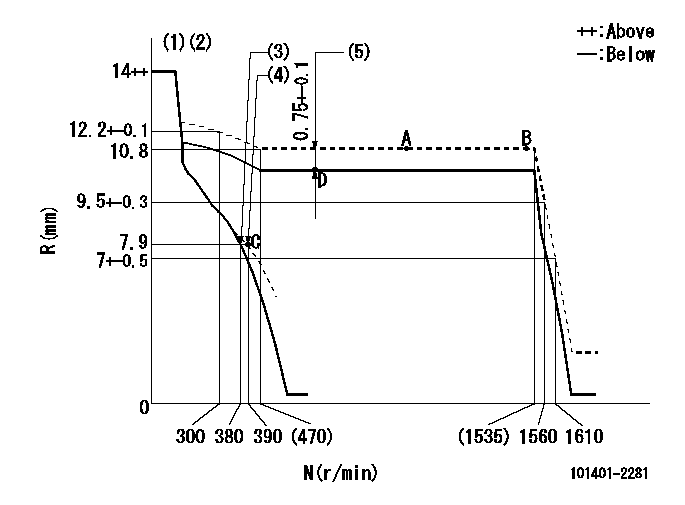
N:Pump speed
R:Rack position (mm)
(1)Target notch: K
(2)Tolerance for racks not indicated: +-0.05mm.
(3)Main spring setting
(4)Set idle sub-spring
(5)Boost compensator stroke (at N = N1)
----------
K=10 N1=650r/min
----------
----------
K=10 N1=650r/min
----------
Speed control lever angle
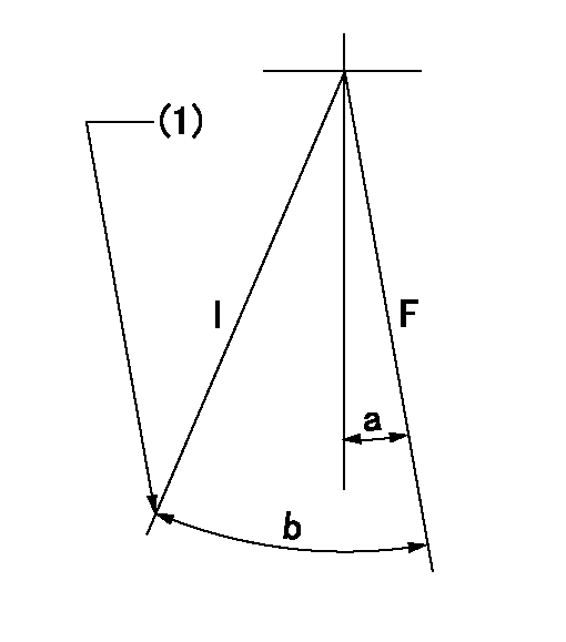
F:Full speed
I:Idle
(1)Stopper bolt setting
----------
----------
a=(12deg)+-5deg b=(26deg)+-5deg
----------
----------
a=(12deg)+-5deg b=(26deg)+-5deg
Stop lever angle

N:Pump normal
S:Stop the pump.
(1)Pump speed aa and rack position bb (to be sealed at delivery)
----------
aa=0r/min bb=1-0.2mm
----------
a=21deg+-5deg b=(55deg)
----------
aa=0r/min bb=1-0.2mm
----------
a=21deg+-5deg b=(55deg)
Timing setting

(1)Pump vertical direction
(2)Position of gear's standard threaded hole at No 1 cylinder's beginning of injection
(3)-
(4)-
----------
----------
a=(70deg)
----------
----------
a=(70deg)
Information:
start by: a) remove fuel injection pump housing and governor 1. Install the fuel injection pump housing on tool (A). 2. Remove the bolt (1) from the cover. Turn the injection pump camshaft until the timing pin (B) can be installed in the camshaft.3. Install tool (C) in the threads of the sleeve (3). Tighten the bolt until the sleeve can be removed.4. Remove the four bolts (4) that hold the body to the housing.5. Remove the body (2) from the housing. 6. Remove the idler gear (5) from the body.7. Remove the O-ring seal (6) from the body. Remove the two lip type seals (7) from the body. 8. Remove the drive gear (9) from the shaft.9. Remove the key (8) from the shaft.Install Fuel Transfer Pump
1. Install the key (1) and the drive gear (2) on the shaft.2. Put 5S1454 Sealing Compound on the outside diameter of the seals. 3. Install the inner seal in the body with the lip of the seal toward the inside with tooling (A).4. Install the outer seal in the body with the lip of the seal toward the outside with tooling (B).5. Remove the extra sealing compound from the body and the seals after installation. 6. Install the O-ring seal (4) and the idler gear (3) in the body. 7. Install the body (5) on the housing. 8. Install the four bolts (7) that hold the body to the housing.9. Put the timing pin (D) in position to keep the camshaft from turning.10. Put the sleeve (6) on the camshaft. 11. Tighten the sleeve into position on the shaft with 4B4280 Washer of tooling (C) approximately .25 in. (6.4 mm). Tighten the sleeve the remainder of the way with the 4N3371 Washer. The 4N3371 Washer is the washer which is on the tachometer drive bolt.
Do not hit the sleeve to install. Damage to governor will result.
12. The end play of the camshaft must be .023 .018 in. (0.58 0.46 mm) after sleeve (6) is installed.end by: a) install fuel injection pump housing and governor
Have questions with 101401-2281?
Group cross 101401-2281 ZEXEL
Hino
Hino
Hino
Hino
Hino
Hino
Hino
101401-2281
INJECTION-PUMP ASSEMBLY