Information injection-pump assembly
ZEXEL
101401-2262
1014012262
HINO
220203691B
220203691b
Rating:
Service parts 101401-2262 INJECTION-PUMP ASSEMBLY:
1.
_
6.
COUPLING PLATE
7.
COUPLING PLATE
8.
_
9.
_
11.
Nozzle and Holder
23600-1710A
12.
Open Pre:MPa(Kqf/cm2)
21.6{220}
15.
NOZZLE SET
Cross reference number
ZEXEL
101401-2262
1014012262
HINO
220203691B
220203691b
Zexel num
Bosch num
Firm num
Name
Calibration Data:
Adjustment conditions
Test oil
1404 Test oil ISO4113 or {SAEJ967d}
1404 Test oil ISO4113 or {SAEJ967d}
Test oil temperature
degC
40
40
45
Nozzle and nozzle holder
105780-8140
Bosch type code
EF8511/9A
Nozzle
105780-0000
Bosch type code
DN12SD12T
Nozzle holder
105780-2080
Bosch type code
EF8511/9
Opening pressure
MPa
17.2
Opening pressure
kgf/cm2
175
Injection pipe
Outer diameter - inner diameter - length (mm) mm 6-2-600
Outer diameter - inner diameter - length (mm) mm 6-2-600
Overflow valve
134424-0920
Overflow valve opening pressure
kPa
162
147
177
Overflow valve opening pressure
kgf/cm2
1.65
1.5
1.8
Tester oil delivery pressure
kPa
157
157
157
Tester oil delivery pressure
kgf/cm2
1.6
1.6
1.6
Direction of rotation (viewed from drive side)
Right R
Right R
Injection timing adjustment
Direction of rotation (viewed from drive side)
Right R
Right R
Injection order
1-3-4-2
Pre-stroke
mm
3.2
3.17
3.23
Beginning of injection position
Drive side NO.1
Drive side NO.1
Difference between angles 1
Cal 1-3 deg. 90 89.75 90.25
Cal 1-3 deg. 90 89.75 90.25
Difference between angles 2
Cal 1-4 deg. 180 179.75 180.25
Cal 1-4 deg. 180 179.75 180.25
Difference between angles 3
Cyl.1-2 deg. 270 269.75 270.25
Cyl.1-2 deg. 270 269.75 270.25
Injection quantity adjustment
Adjusting point
A
Rack position
10.5
Pump speed
r/min
900
900
900
Average injection quantity
mm3/st.
83.5
81.5
85.5
Max. variation between cylinders
%
0
-3
3
Basic
*
Fixing the lever
*
Boost pressure
kPa
50.7
50.7
Boost pressure
mmHg
380
380
Injection quantity adjustment_02
Adjusting point
C
Rack position
7.9+-0.5
Pump speed
r/min
325
325
325
Average injection quantity
mm3/st.
8
6.5
9.5
Max. variation between cylinders
%
0
-15
15
Fixing the rack
*
Boost pressure
kPa
0
0
0
Boost pressure
mmHg
0
0
0
Boost compensator adjustment
Pump speed
r/min
650
650
650
Rack position
R1-1.2
Boost pressure
kPa
13.3
10.6
16
Boost pressure
mmHg
100
80
120
Boost compensator adjustment_02
Pump speed
r/min
650
650
650
Rack position
R1(10.5)
Boost pressure
kPa
37.3
37.3
37.3
Boost pressure
mmHg
280
280
280
Timer adjustment
Pump speed
r/min
1350--
Advance angle
deg.
0
0
0
Remarks
Start
Start
Timer adjustment_02
Pump speed
r/min
1300
Advance angle
deg.
0.3
Timer adjustment_03
Pump speed
r/min
1500
Advance angle
deg.
2.5
2
3
Timer adjustment_04
Pump speed
r/min
-
Advance angle
deg.
3.5
3.5
3.5
Remarks
Measure the actual speed, stop
Measure the actual speed, stop
Test data Ex:
Governor adjustment
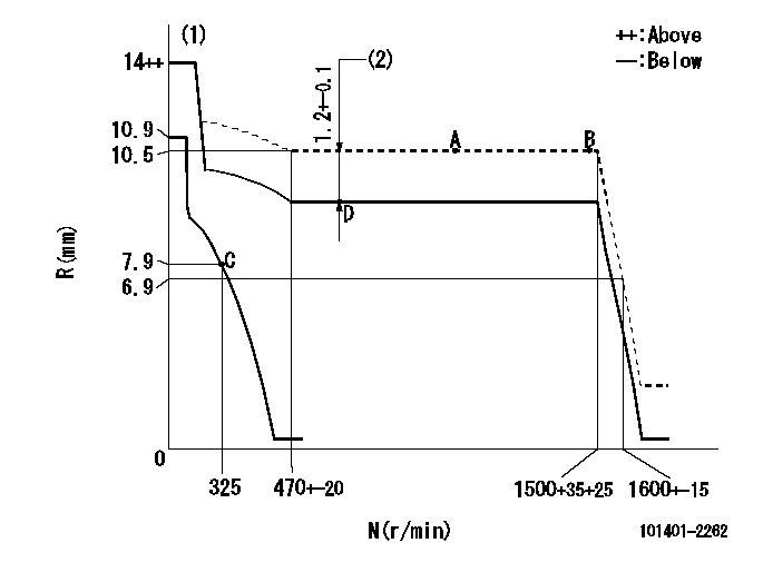
N:Pump speed
R:Rack position (mm)
(1)Target notch: K
(2)Boost compensator stroke (at N = N1)
----------
K=7 N1=650r/min
----------
----------
K=7 N1=650r/min
----------
Speed control lever angle

F:Full speed
I:Idle
(1)Stopper bolt setting
----------
----------
a=8deg+-5deg b=28deg+-5deg
----------
----------
a=8deg+-5deg b=28deg+-5deg
Stop lever angle

N:Pump normal
S:Stop the pump.
(1)Pump speed aa and rack position bb (to be sealed at delivery)
----------
aa=0r/min bb=1-0.2mm
----------
a=21deg+-5deg b=(55deg)
----------
aa=0r/min bb=1-0.2mm
----------
a=21deg+-5deg b=(55deg)
Timing setting

(1)Pump vertical direction
(2)Position of gear's standard threaded hole at No 1 cylinder's beginning of injection
(3)-
(4)-
----------
----------
a=(70deg)
----------
----------
a=(70deg)
Information:
Start By:a. remove timing gear coverb. remove fuel injection pump housing and governor 1. Remove four bolts (2), plate (3) and idler gear (1). 2. If the camshaft is not going to be removed, use Tool (A) to remove camshaft gear (4).
Do not turn the crankshaft with the camshaft gear removed. Damage can be caused to the pistons and valves or both.
3. Remove bolts (5) that hold timing gear plate (6) to the cylinder block.4. Remove timing gear plate (6). 5. Use Tool (B) to remove the bearing from the idler gear. The following steps are for the installation of the timing gears and plate.6. Install a new gasket on the timing gear plate.7. Put timing gear plate (6) in position on the cylinder block and install the bolts that hold the timing gear plate to the cylinder block.8. Heat camshaft gear (4) to a maximum temperature of 205° C (400° F) for no longer than three hours and install it on the camshaft.9. Use Tool (B) and install the bearing in the idler gear. Set the gear on the front face (face with the timing marks). Drive the bearing from the rear face toward the front face of the gear. Install the bearing to a depth of 1.5 0.5 mm (.06 .02 in) below the rear face of the idler gear.10. Install the idler gear, plate and bolts. Be sure No. 1 cylinder is at top center on the compression stroke. Install the idler gear so "V" mark (7) on the idler gear is in alignment with the "V" mark on the crankshaft gear. "K" marks (8) on the camshaft gear can be seen at the outer edges of the idler gear.End By:a. install fuel injection pump housing and governorb. install timing gear cover