Information injection-pump assembly
ZEXEL
101401-2160
1014012160
Rating:
Service parts 101401-2160 INJECTION-PUMP ASSEMBLY:
1.
_
6.
COUPLING PLATE
7.
COUPLING PLATE
8.
_
9.
_
11.
Nozzle and Holder
23600-1710
12.
Open Pre:MPa(Kqf/cm2)
21.6{220}
15.
NOZZLE SET
Cross reference number
ZEXEL
101401-2160
1014012160
Zexel num
Bosch num
Firm num
Name
101401-2160
INJECTION-PUMP ASSEMBLY
Calibration Data:
Adjustment conditions
Test oil
1404 Test oil ISO4113 or {SAEJ967d}
1404 Test oil ISO4113 or {SAEJ967d}
Test oil temperature
degC
40
40
45
Nozzle and nozzle holder
105780-8140
Bosch type code
EF8511/9A
Nozzle
105780-0000
Bosch type code
DN12SD12T
Nozzle holder
105780-2080
Bosch type code
EF8511/9
Opening pressure
MPa
17.2
Opening pressure
kgf/cm2
175
Injection pipe
Outer diameter - inner diameter - length (mm) mm 6-2-600
Outer diameter - inner diameter - length (mm) mm 6-2-600
Overflow valve
134424-0920
Overflow valve opening pressure
kPa
162
147
177
Overflow valve opening pressure
kgf/cm2
1.65
1.5
1.8
Tester oil delivery pressure
kPa
157
157
157
Tester oil delivery pressure
kgf/cm2
1.6
1.6
1.6
Direction of rotation (viewed from drive side)
Right R
Right R
Injection timing adjustment
Direction of rotation (viewed from drive side)
Right R
Right R
Injection order
1-3-4-2
Pre-stroke
mm
3.2
3.17
3.23
Beginning of injection position
Drive side NO.1
Drive side NO.1
Difference between angles 1
Cal 1-3 deg. 90 89.75 90.25
Cal 1-3 deg. 90 89.75 90.25
Difference between angles 2
Cal 1-4 deg. 180 179.75 180.25
Cal 1-4 deg. 180 179.75 180.25
Difference between angles 3
Cyl.1-2 deg. 270 269.75 270.25
Cyl.1-2 deg. 270 269.75 270.25
Injection quantity adjustment
Adjusting point
-
Rack position
10.4
Pump speed
r/min
900
900
900
Average injection quantity
mm3/st.
75.1
73.1
77.1
Max. variation between cylinders
%
0
-3
3
Basic
*
Fixing the rack
*
Standard for adjustment of the maximum variation between cylinders
*
Injection quantity adjustment_02
Adjusting point
H
Rack position
8+-0.5
Pump speed
r/min
300
300
300
Average injection quantity
mm3/st.
9
7.5
10.5
Max. variation between cylinders
%
0
-15
15
Fixing the rack
*
Standard for adjustment of the maximum variation between cylinders
*
Injection quantity adjustment_03
Adjusting point
A
Rack position
R1(10.4)
Pump speed
r/min
900
900
900
Average injection quantity
mm3/st.
75.1
74.1
76.1
Basic
*
Fixing the lever
*
Boost pressure
kPa
24
24
Boost pressure
mmHg
180
180
Injection quantity adjustment_04
Adjusting point
B
Rack position
R1(10.4)
Pump speed
r/min
1600
1600
1600
Average injection quantity
mm3/st.
85.2
81.2
89.2
Fixing the lever
*
Boost pressure
kPa
24
24
Boost pressure
mmHg
180
180
Injection quantity adjustment_05
Adjusting point
C
Rack position
R1-0.25
Pump speed
r/min
720
720
720
Average injection quantity
mm3/st.
62.5
58.5
66.5
Fixing the lever
*
Boost pressure
kPa
24
24
Boost pressure
mmHg
180
180
Injection quantity adjustment_06
Adjusting point
D
Rack position
R2-1.2
Pump speed
r/min
720
720
720
Average injection quantity
mm3/st.
43.2
39.2
47.2
Fixing the lever
*
Boost pressure
kPa
0
0
0
Boost pressure
mmHg
0
0
0
Injection quantity adjustment_07
Adjusting point
E
Rack position
R1+0.25
Pump speed
r/min
1080
1080
1080
Average injection quantity
mm3/st.
81.2
77.2
85.2
Fixing the lever
*
Boost pressure
kPa
24
24
Boost pressure
mmHg
180
180
Injection quantity adjustment_08
Adjusting point
F
Rack position
R1+0.1
Pump speed
r/min
1300
1300
1300
Average injection quantity
mm3/st.
82.7
80.7
84.7
Fixing the lever
*
Boost pressure
kPa
24
24
Boost pressure
mmHg
180
180
Injection quantity adjustment_09
Adjusting point
I
Rack position
-
Pump speed
r/min
100
100
100
Average injection quantity
mm3/st.
110
110
120
Fixing the lever
*
Rack limit
*
Boost compensator adjustment
Pump speed
r/min
720
720
720
Rack position
R2-1.2
Boost pressure
kPa
2
2
4.7
Boost pressure
mmHg
15
15
35
Boost compensator adjustment_02
Pump speed
r/min
720
720
720
Rack position
R2(R1-0.
25)
Boost pressure
kPa
10.7
10.7
10.7
Boost pressure
mmHg
80
80
80
Timer adjustment
Pump speed
r/min
1300+50
Advance angle
deg.
0
0
0
Remarks
Start
Start
Timer adjustment_02
Pump speed
r/min
1600
Advance angle
deg.
3.5
3.2
3.8
Remarks
Finish
Finish
Test data Ex:
Governor adjustment
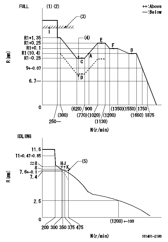
N:Pump speed
R:Rack position (mm)
(1)Torque cam stamping: T1
(2)Tolerance for racks not indicated: +-0.05mm.
(3)RACK LIMIT
(4)Boost compensator stroke: BCL
(5)Idle increase set point (air cylinder's negative pressure supply: P1)
----------
T1=D64 BCL=1.2+-0.1mm P1=392+98kPa(4+1kg/cm2)
----------
----------
T1=D64 BCL=1.2+-0.1mm P1=392+98kPa(4+1kg/cm2)
----------
Speed control lever angle

F:Full speed
I:Idle
(1)Stopper bolt set position 'H'
----------
----------
a=21.5deg+-5deg b=43deg+-3deg
----------
----------
a=21.5deg+-5deg b=43deg+-3deg
Stop lever angle

N:Pump normal
S:Stop the pump.
----------
----------
a=40deg+-5deg b=40deg+-5deg
----------
----------
a=40deg+-5deg b=40deg+-5deg
0000001501 AIR CYLINDER

(A): Speed lever
(B): Set bolt
(C): air cylinder
(D): nut
(E): fix
1. Air cylinder adjustment procedure
(1)With the speed lever in the idling position, temporarily set the clearance between speed lever (A) and set bolt (B) at approximately L1.
(2)Set the speed to N1 and supply positive pressure P1 to the air cylinder (C).
(3)Gradually push set bolt (B) out (approximately L2) and tighten nut (D) where the speed is N2 and the rack position is Ra.
(4)Apply positive pressure P1 several times.
(5)Confirm that the lever returns to the idle position at positive pressure P2.
(6)Also, confirm that the rack position is Rb at air pressure P1.
----------
L1=(9)mm L2=(6)mm Ra=7.5~7.7mm Rb=7.5~7.7mm N1=475r/min N2=475r/min P1=392+98kPa(4+1kgf/cm2) P2=0kPa(0kgf/cm2)
----------
----------
L1=(9)mm L2=(6)mm Ra=7.5~7.7mm Rb=7.5~7.7mm N1=475r/min N2=475r/min P1=392+98kPa(4+1kgf/cm2) P2=0kPa(0kgf/cm2)
----------
Timing setting

(1)Pump vertical direction
(2)Position of gear's standard threaded hole at No 1 cylinder's beginning of injection
(3)-
(4)-
----------
----------
a=(70deg)
----------
----------
a=(70deg)
Information:
January 9, 2003
O-10
Priority PRODUCT IMPROVEMENT PROGRAM FOR INSTALLINGA NEW WIRE ASSEMBLY IN THE INJECTION ACTUATION PRESSURE CONTROL ON CERTAIN325C AND 325C L EXCAVATORS AND 950G II AND 962G II WHEEL LOADERS
1408 PI30431
This Program must be administered assoon as possible. When reporting the repair, use "PI30431" as the Partnumber and "7751" as the Group Number, "56" as the Warranty Claim DescriptionCode and "T" as the SIMS Description Code. Exception: If the repair isdone after failure, use "PI30431" as the Part Number, "7751" as the GroupNumber, "96" as the Warranty Claim Description Code, and "Z" as the SIMSDescription Code. The information supplied in this serviceletter may not be valid after the termination date of this program. Donot perform the work outlined in this Service Letter after the terminationdate without first contacting your Caterpillar product analyst.
COMPLETION DATE
TERMINATION DATE
July 31, 2003 January 31, 2004PROBLEM
A new wire assembly needs to be installed in theinjection actuation pressure control on certain 325C and 325C L Excavatorsand 950G II and 962G II Wheel Loaders. The injection actuation pressurecontrol valve connector may have been assembled incorrectly some 3126BEngine harness. This can lead to intermittent engine operation or can causethe engine to stop. The wire assembly must be replaced.AFFECTED PRODUCT
Model Identification Number
325C L CRB465, 466, 468, 469
325C CSJ571, 572, 574, 578, 582, 586
950G II AYL587, 591, 592, 598-601,610, 612, 615AYB486-491
962G AYE459
962G II BAB336, 338PARTS NEEDED
1 - 2324367 Wire AssemblyACTION REQUIRED
See the attached Rework Procedure.SERVICE CLAIM ALLOWANCES
Caterpillar Dealer Suggested Customer Suggested
Parts Labor Hrs. Parts Labor Hrs. Parts Labor Hrs.
100% 1 0 0 0 0
This is a 1-hour job.PARTS DISPOSITION
Handle the parts in accordance with your WarrantyBulletin on warranty parts handling.
MAKE EVERY EFFORT TO COMPLETE THIS PROGRAMAS SOON AS POSSIBLE.Attach. (1-Sample of Owner Notification)
(2-Rework Procedure)SAMPLE OF OWNER NOTIFICATION
XYZ Corporation
3240 Arrow Drive
Anywhere, YZ 99999PRIORITY - Install A New Wire Assembly In TheInjection Actuation Pressure ControlMODELS INVOLVED - 325C and 325C L Excavatorsand 950G II and 962G II Wheel LoadersDear Caterpillar Product Owner:A new wire assembly needs to be installed inthe injection actuation pressure control on certain 325C and 325C L Excavatorsand 950G II and 962G II Wheel Loaders. The injection actuation pressurecontrol valve connector may have been assembled incorrectly some 3126BEngine harness. This can lead to intermittent engine operation or can causethe engine to stop. The wire assembly must be replaced. A new wire assemblyneeds to be installed on the products listed below. You will not be chargedfor the service performed.Contact your local Caterpillar dealer immediatelyto schedule this service. The dealer will advise you of the time requiredto complete this service. Please refer the dealer to their Service Letterdated January 9, 2003 when scheduling this service.We regret the inconvenience this may causeyou, but urge you to have this service performed as soon as possible toprevent unscheduled downtime.Caterpillar Inc.
Identification #(s)Attached to January 9, 2003 Service Letter
Rework Procedure
Disconnect the IAP control valve connector (seeIllustration 1).
Cut the wires behind the connector.
Strip the ends of both wires.
Install 2324367 harness by crimping the strippedwires inside the splice. Take care to connect pink wire to pink wire onone hand, purple wire to purple wire on the other hand.
Heat both heat shrinkable tubes in order to insulateboth splices.
Reconnect the
Have questions with 101401-2160?
Group cross 101401-2160 ZEXEL
Hino
Hino
Hino
Hino
Hino
Hino
101401-2160
INJECTION-PUMP ASSEMBLY