Information injection-pump assembly
ZEXEL
101401-2121
1014012121
HINO
220005771A
220005771a
Rating:
Service parts 101401-2121 INJECTION-PUMP ASSEMBLY:
1.
_
6.
COUPLING PLATE
7.
COUPLING PLATE
8.
_
9.
_
11.
Nozzle and Holder
23600-1981
12.
Open Pre:MPa(Kqf/cm2)
21.6{220}
15.
NOZZLE SET
Cross reference number
ZEXEL
101401-2121
1014012121
HINO
220005771A
220005771a
Zexel num
Bosch num
Firm num
Name
Calibration Data:
Adjustment conditions
Test oil
1404 Test oil ISO4113 or {SAEJ967d}
1404 Test oil ISO4113 or {SAEJ967d}
Test oil temperature
degC
40
40
45
Nozzle and nozzle holder
105780-8140
Bosch type code
EF8511/9A
Nozzle
105780-0000
Bosch type code
DN12SD12T
Nozzle holder
105780-2080
Bosch type code
EF8511/9
Opening pressure
MPa
17.2
Opening pressure
kgf/cm2
175
Injection pipe
Outer diameter - inner diameter - length (mm) mm 6-2-600
Outer diameter - inner diameter - length (mm) mm 6-2-600
Overflow valve
134424-0920
Overflow valve opening pressure
kPa
162
147
177
Overflow valve opening pressure
kgf/cm2
1.65
1.5
1.8
Tester oil delivery pressure
kPa
157
157
157
Tester oil delivery pressure
kgf/cm2
1.6
1.6
1.6
Direction of rotation (viewed from drive side)
Right R
Right R
Injection timing adjustment
Direction of rotation (viewed from drive side)
Right R
Right R
Injection order
1-3-4-2
Pre-stroke
mm
4.4
4.37
4.43
Beginning of injection position
Drive side NO.1
Drive side NO.1
Difference between angles 1
Cal 1-3 deg. 90 89.75 90.25
Cal 1-3 deg. 90 89.75 90.25
Difference between angles 2
Cal 1-4 deg. 180 179.75 180.25
Cal 1-4 deg. 180 179.75 180.25
Difference between angles 3
Cyl.1-2 deg. 270 269.75 270.25
Cyl.1-2 deg. 270 269.75 270.25
Injection quantity adjustment
Adjusting point
-
Rack position
12.1
Pump speed
r/min
1100
1100
1100
Average injection quantity
mm3/st.
98.5
96.5
100.5
Max. variation between cylinders
%
0
-3
3
Basic
*
Fixing the rack
*
Standard for adjustment of the maximum variation between cylinders
*
Injection quantity adjustment_02
Adjusting point
H
Rack position
9.2+-0.5
Pump speed
r/min
325
325
325
Average injection quantity
mm3/st.
20.8
19.3
22.3
Max. variation between cylinders
%
0
-15
15
Fixing the rack
*
Standard for adjustment of the maximum variation between cylinders
*
Injection quantity adjustment_03
Adjusting point
A
Rack position
R1(12.1)
Pump speed
r/min
1100
1100
1100
Average injection quantity
mm3/st.
98.5
97.5
99.5
Basic
*
Fixing the lever
*
Boost pressure
kPa
22.7
22.7
Boost pressure
mmHg
170
170
Injection quantity adjustment_04
Adjusting point
B
Rack position
R1-0.1
Pump speed
r/min
1600
1600
1600
Average injection quantity
mm3/st.
93.7
89.7
97.7
Fixing the lever
*
Boost pressure
kPa
22.7
22.7
Boost pressure
mmHg
170
170
Injection quantity adjustment_05
Adjusting point
C
Rack position
R1-1.25
Pump speed
r/min
650
650
650
Average injection quantity
mm3/st.
67.3
63.3
71.3
Fixing the lever
*
Boost pressure
kPa
22.7
22.7
Boost pressure
mmHg
170
170
Injection quantity adjustment_06
Adjusting point
D
Rack position
R1-1
Pump speed
r/min
400
400
400
Average injection quantity
mm3/st.
78.1
74.1
82.1
Fixing the lever
*
Boost pressure
kPa
22.7
22.7
Boost pressure
mmHg
170
170
Injection quantity adjustment_07
Adjusting point
E
Rack position
-
Pump speed
r/min
400
400
400
Average injection quantity
mm3/st.
52
48
56
Fixing the lever
*
Boost pressure
kPa
0
0
0
Boost pressure
mmHg
0
0
0
Injection quantity adjustment_08
Adjusting point
F
Rack position
R2-0.95
Pump speed
r/min
650
650
650
Average injection quantity
mm3/st.
43.4
39.4
47.4
Fixing the lever
*
Boost pressure
kPa
0
0
0
Boost pressure
mmHg
0
0
0
Injection quantity adjustment_09
Adjusting point
I
Rack position
-
Pump speed
r/min
100
100
100
Average injection quantity
mm3/st.
115
115
130
Fixing the lever
*
Rack limit
*
Boost compensator adjustment
Pump speed
r/min
650
650
650
Rack position
R2-0.95
Boost pressure
kPa
2
2
4.7
Boost pressure
mmHg
15
15
35
Boost compensator adjustment_02
Pump speed
r/min
650
650
650
Rack position
R2(R1-1.
25)
Boost pressure
kPa
9.3
9.3
9.3
Boost pressure
mmHg
70
70
70
Timer adjustment
Pump speed
r/min
1350--
Advance angle
deg.
0
0
0
Remarks
Start
Start
Timer adjustment_02
Pump speed
r/min
1300
Advance angle
deg.
0.3
Timer adjustment_03
Pump speed
r/min
1600
Advance angle
deg.
2.5
2.2
2.8
Remarks
Finish
Finish
Test data Ex:
Governor adjustment
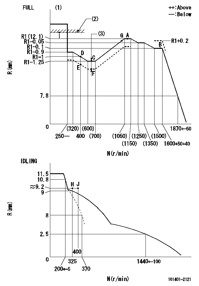
N:Pump speed
R:Rack position (mm)
(1)Torque cam stamping: T1
(2)RACK LIMIT
(3)Boost compensator stroke: BCL
----------
T1=D13 BCL=0.95+-0.1mm
----------
----------
T1=D13 BCL=0.95+-0.1mm
----------
Speed control lever angle

F:Full speed
I:Idle
(1)Use the hole at R = aa
(2)Stopper bolt set position 'H'
----------
aa=50mm
----------
a=34deg+-5deg b=40deg+-3deg
----------
aa=50mm
----------
a=34deg+-5deg b=40deg+-3deg
Stop lever angle
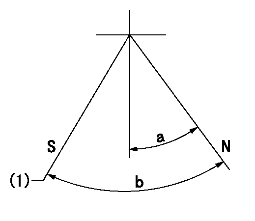
N:Engine normal (pump normal)
S:Engine stop
(1)Set the stopper screw. (After setting, apply red paint.)
----------
----------
a=20deg+-5deg b=26deg+-5deg
----------
----------
a=20deg+-5deg b=26deg+-5deg
0000001501 TAMPER PROOF
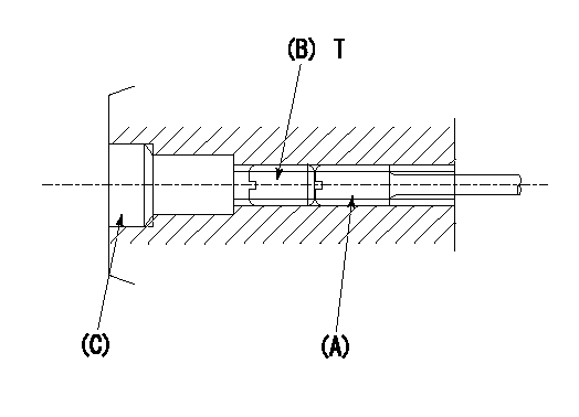
1. Method for setting tamperproof proofing
(1)After governor adjustment (torque cam phase adjustment), move the load lever to increase the full rack position to Ra.
(2)At pump speed N1, push in the screw (A) until the rack position is Rb.
(3)Temporarily caulk using the tip of a screwdriver
(4)Confirm that the rack at that time is at Rc.
(5)Lock using setscrew (B). (Tightening torque = T)
(6)Next, coat (C) with adhesive and then pressfit.
(7)Then, readjust the full rack position using the load lever.
----------
N1=1600r/min Ra=1mm Rb=R1(12.1)+0.2mm Rc=R1(12.1)+0.2mm
----------
T=4.9~6.9N-m(0.5~0.7Kgf-m)
----------
N1=1600r/min Ra=1mm Rb=R1(12.1)+0.2mm Rc=R1(12.1)+0.2mm
----------
T=4.9~6.9N-m(0.5~0.7Kgf-m)
0000001601 ACTUATOR
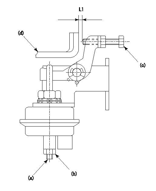
(a) Screw
(B) Nut
(c) set bolt
(d) control lever
1. Actuator adjustment procedure
(1)Position the control lever (d) in the idling position.
(2)Set the clearance between the control lever (d) and the set bolt (c) to approx. L1.
(3)Loosen the nut (b) and fully tighten the screw (a).
(4)Set the pump speed at N1and measure the rack position when negative pressure P1 is applied to the actuator.
(5)Loosen screw (a) and fix the nut (b) when the pump speed is N2 and the rack position is R1.
(6)Confirm that control lever (d) returns to the idling position at actuator negative pressure 0.
(7)Repeat procedures (4) to (6) several times and confirm that the control lever (d) moves smoothly.
----------
L1=2mm R1=10.1~10.4mm P1=66.7kPa(500mmHg) N1=325r/min N2=325r/min
----------
----------
L1=2mm R1=10.1~10.4mm P1=66.7kPa(500mmHg) N1=325r/min N2=325r/min
----------
Timing setting

(1)Pump vertical direction
(2)Position of gear's standard threaded hole at No 1 cylinder's beginning of injection
(3)-
(4)-
----------
----------
a=(70deg)
----------
----------
a=(70deg)
Information:
Start By:a. remove oil pumpb. remove oil pan plate 1. Remove No. 1, 3, 5 and 7 main bearing caps (1). Remove the lower halves of the main bearings from the main bearing caps.
If the crankshaft is turned in the wrong direction, the tab on the bearing will be pushed between the crankshaft and the bearing area in the cylinder block. This can result in damage to the cylinder block and/or the crankshaft.
2. Install Tool (A) in the hole in the crankshaft journal, and turn the crankshaft to remove the upper halves of main bearings (2).3. Remove crankshaft thrust bearings (3) from the rear main bearing. Install the main bearings dry when the clearance checks are made. Put clean engine oil on the main bearings for final assembly.
Make sure the upper and lower halves of the main bearings are installed so the bearing tabs fit into the notch in the cylinder block and the main bearing caps.
4. Use Tool (A), and install new upper halves of main bearings (2) in the cylinder block. Install new lower halves of main bearings (2) in main bearing caps (1).
When the bearing clearance is checked and the engine is in an upright position (vertical position with cylinder head on top), the crankshaft will have to be lifted up and held against the upper halves of the main bearings to get a correct measurement with the Plastigage. The Plastigage will not hold the weight of the crankshaft and give a correct indication. If the engine is in a horizontal position, it is not necessary to hold the crankshaft up. Do not turn the crankshaft when the Plastigage is in position to check clearances.
For complete details concerning measuring bearing clearances, see Engine Bearings And Crankshafts, Form No. SEBD0531.5. Check the main bearing clearance with Plastigage (B) as follows:a. Put a piece of Plastigage (B) on the crankshaft journals as shown.
Make sure the part number on the main bearing cap is toward the front of the engine and the number on the main bearing cap is the same as the number on the cylinder block on the left side of each main bearing cap.
b. Put main bearing caps (1) in position in the engine. Put 2P2506 Thread Lubricant on the bolt threads and the face of the washers. Install the bolts. Tighten the bolts to a torque of 40 4 N m (30 3 lb ft).c. Put a mark on each bolt and main bearing cap; then tighten the bolts 90° more.d. Remove the main bearing caps, and measure the Plastigage to find the bearing clearance. The main bearing clearance for new bearings must be 0.076 to 0.165 mm (.0030 to .0065 in.). Maximum permissible clearance with used bearings is 0.25 mm (.010 in.). 6. Put clean oil on the thrust bearing, and install a new thrust bearing for the rear main bearing. Install the thrust bearing with the identification "BLOCK SIDE" toward the cylinder block and the tabs on the thrust bearings