Information injection-pump assembly
BOSCH
9 400 613 646
9400613646
ZEXEL
101401-2111
1014012111
HINO
220005660A
220005660a
Rating:
Service parts 101401-2111 INJECTION-PUMP ASSEMBLY:
1.
_
6.
COUPLING PLATE
7.
COUPLING PLATE
8.
_
9.
_
11.
Nozzle and Holder
12.
Open Pre:MPa(Kqf/cm2)
21.6(220)
15.
NOZZLE SET
Cross reference number
BOSCH
9 400 613 646
9400613646
ZEXEL
101401-2111
1014012111
HINO
220005660A
220005660a
Zexel num
Bosch num
Firm num
Name
101401-2111
9 400 613 646
220005660A HINO
INJECTION-PUMP ASSEMBLY
W04C-T K
W04C-T K
Calibration Data:
Adjustment conditions
Test oil
1404 Test oil ISO4113 or {SAEJ967d}
1404 Test oil ISO4113 or {SAEJ967d}
Test oil temperature
degC
40
40
45
Nozzle and nozzle holder
105780-8140
Bosch type code
EF8511/9A
Nozzle
105780-0000
Bosch type code
DN12SD12T
Nozzle holder
105780-2080
Bosch type code
EF8511/9
Opening pressure
MPa
17.2
Opening pressure
kgf/cm2
175
Injection pipe
Outer diameter - inner diameter - length (mm) mm 6-2-600
Outer diameter - inner diameter - length (mm) mm 6-2-600
Overflow valve
134424-0920
Overflow valve opening pressure
kPa
162
147
177
Overflow valve opening pressure
kgf/cm2
1.65
1.5
1.8
Tester oil delivery pressure
kPa
157
157
157
Tester oil delivery pressure
kgf/cm2
1.6
1.6
1.6
Direction of rotation (viewed from drive side)
Right R
Right R
Injection timing adjustment
Direction of rotation (viewed from drive side)
Right R
Right R
Injection order
1-3-4-2
Pre-stroke
mm
3.2
3.17
3.23
Beginning of injection position
Drive side NO.1
Drive side NO.1
Difference between angles 1
Cal 1-3 deg. 90 89.75 90.25
Cal 1-3 deg. 90 89.75 90.25
Difference between angles 2
Cal 1-4 deg. 180 179.75 180.25
Cal 1-4 deg. 180 179.75 180.25
Difference between angles 3
Cyl.1-2 deg. 270 269.75 270.25
Cyl.1-2 deg. 270 269.75 270.25
Injection quantity adjustment
Adjusting point
-
Rack position
10.7
Pump speed
r/min
900
900
900
Average injection quantity
mm3/st.
78.5
76.5
80.5
Max. variation between cylinders
%
0
-3
3
Basic
*
Fixing the rack
*
Standard for adjustment of the maximum variation between cylinders
*
Injection quantity adjustment_02
Adjusting point
H
Rack position
8+-0.5
Pump speed
r/min
300
300
300
Average injection quantity
mm3/st.
9
7.5
10.5
Max. variation between cylinders
%
0
-15
15
Fixing the rack
*
Standard for adjustment of the maximum variation between cylinders
*
Injection quantity adjustment_03
Adjusting point
A
Rack position
R1(10.7)
Pump speed
r/min
900
900
900
Average injection quantity
mm3/st.
78.5
77.5
79.5
Basic
*
Fixing the lever
*
Boost pressure
kPa
24
24
Boost pressure
mmHg
180
180
Injection quantity adjustment_04
Adjusting point
B
Rack position
R1-0.5
Pump speed
r/min
1600
1600
1600
Average injection quantity
mm3/st.
84.5
82.5
86.5
Fixing the lever
*
Boost pressure
kPa
24
24
Boost pressure
mmHg
180
180
Injection quantity adjustment_05
Adjusting point
C
Rack position
R1-0.25
Pump speed
r/min
1300
1300
1300
Average injection quantity
mm3/st.
82.3
78.3
86.3
Fixing the lever
*
Boost pressure
kPa
24
24
Boost pressure
mmHg
180
180
Injection quantity adjustment_06
Adjusting point
D
Rack position
R1-0.5
Pump speed
r/min
650
650
650
Average injection quantity
mm3/st.
62.7
58.7
66.7
Fixing the lever
*
Boost pressure
kPa
24
24
Boost pressure
mmHg
180
180
Injection quantity adjustment_07
Adjusting point
E
Rack position
-
Pump speed
r/min
400
400
400
Average injection quantity
mm3/st.
50
48
52
Fixing the lever
*
Boost pressure
kPa
0
0
0
Boost pressure
mmHg
0
0
0
Injection quantity adjustment_08
Adjusting point
I
Rack position
14.3+-0.
5
Pump speed
r/min
100
100
100
Average injection quantity
mm3/st.
110
110
120
Fixing the lever
*
Rack limit
*
Injection quantity adjustment_09
Adjusting point
K
Rack position
R2(9)
Pump speed
r/min
650
650
650
Average injection quantity
mm3/st.
39.3
35.3
43.3
Fixing the lever
*
Boost pressure
kPa
0
0
0
Boost pressure
mmHg
0
0
0
Boost compensator adjustment
Pump speed
r/min
650
650
650
Rack position
R2(9)
Boost pressure
kPa
2
2
4.7
Boost pressure
mmHg
15
15
35
Boost compensator adjustment_02
Pump speed
r/min
650
650
650
Rack position
R1-0.5
Boost pressure
kPa
10.7
10.7
10.7
Boost pressure
mmHg
80
80
80
Timer adjustment
Pump speed
r/min
1300+50
Advance angle
deg.
0
0
0
Remarks
Start
Start
Timer adjustment_02
Pump speed
r/min
1600
Advance angle
deg.
3.5
3.2
3.8
Remarks
Finish
Finish
Test data Ex:
Governor adjustment
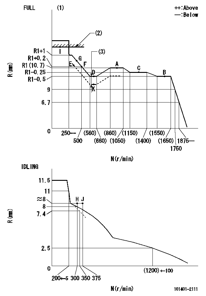
N:Pump speed
R:Rack position (mm)
(1)Torque cam stamping: T1
(2)RACK LIMIT
(3)Boost compensator stroke: BCL
----------
T1=C04 BCL=(1.2)+-0.1mm
----------
----------
T1=C04 BCL=(1.2)+-0.1mm
----------
Speed control lever angle
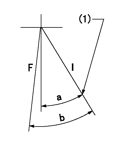
F:Full speed
I:Idle
(1)Stopper bolt set position 'H'
----------
----------
a=34deg+-5deg b=42deg+-3deg
----------
----------
a=34deg+-5deg b=42deg+-3deg
Stop lever angle
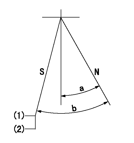
N:Engine normal (pump normal)
S:Engine stop
(1)Set the stopper screw.
(2)(Apply red paint after setting.)
----------
----------
a=20deg+-5deg b=(29deg)+-5deg
----------
----------
a=20deg+-5deg b=(29deg)+-5deg
0000001501 LEVER
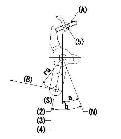
(N) Engine normal (pump normal)
(S) Engine stop
(A) stopper screw
(B) Stop direction (perpendicular)
Stop lever adjusting procedure
(1)After completing adjustment, confirm that the engine's normal lever angle (pump's normal lever) is within the specifications in the figure above.
(2)With the speed lever at Full and the pump speed at Na (specified speed), temporarily set the stopper screw (A) at the rack position Ra.
(3)Turn the stopper screw (A) Rb in the stop direction (Nb turns) and set it. Measure the rack position. (Rack position = approx. Rc)
(4)After setting, confirm non-injection with the speed lever at idle and pump speed at Nc.
(5)After adjustment, apply red paint.
----------
Na=- Ra=4.9mm Rb=1.5mm Nb=1.5 Rc=2.9mm Nc=300r/min
----------
ra=37mm a=20deg+-5deg b=(29deg)+-5deg
----------
Na=- Ra=4.9mm Rb=1.5mm Nb=1.5 Rc=2.9mm Nc=300r/min
----------
ra=37mm a=20deg+-5deg b=(29deg)+-5deg
Timing setting

(1)Pump vertical direction
(2)Position of gear's standard threaded hole at No 1 cylinder's beginning of injection
(3)-
(4)-
----------
----------
a=(70deg)
----------
----------
a=(70deg)
Information:
2. Turn the crankshaft until two of the pistons are at bottom center. Remove the nuts and bolts (1) from the connecting rods that are at bottom center. Remove connecting rod caps (2). Put identification marks on them for installation purposes.
Do not let the connecting rods hit the crankshaft or the bottom edge of the cylinder liners when the pistons are removed.
3. Push the connecting rods and pistons away from the crankshaft until the piston rings are out of the cylinder liners. Remove the two pistons from the engine.4. Keep each connecting rod cap with its respective connecting rod and piston. Put identification marks on each piston as to its location in the engine.5. Do Steps 1 through 4 for the removal of the remaining pistons.Install Pistons & Connecting Rods
1. Turn the crankshaft until the bearing journals for the pistons to be installed are at bottom center.2. Put clean engine oil on the crankshaft journals and on the inside of the cylinder liners. Put clean engine oil on the piston rings and the connecting rod bearings.3. Move the piston rings on the pistons until the ring openings are approximately 90° apart. 4. Put the piston in the cylinder liner with the "V" mark on the piston in alignment with the "V" mark on the cylinder block. Put Tool (A) in position on the cylinder block and compress the piston rings.5. Push the piston into the cylinder liner and out of the ring compressor. 6. Pull the connecting rod into position on the crankshaft as shown. Install connecting rod bolts (1) in the connecting rods.7. Put clean engine oil on the lower half of the connecting rod bearing. Put 2P2506 Thread Lubricant on the bolt threads and on the surfaces of the nuts that make contact with the connecting rod caps.
When the connecting rod caps are installed, make sure the number on the side of the cap is next to and respective with the number on the side of the connecting rod.
8. Install connecting rod caps (2) and the nuts that hold them. Tighten the nuts to a torque of 40 4 N m (30 3 lb ft). Put a mark on each nut as to its location. Tighten them 90° 5° more.9. Do Steps 1 through 8 for the remainder of the pistons.End By:a. install oil pumpb. install oil pan platec. install cylinder head assembly and spacer plateDisassemble Pistons & Connecting Rods
Start By:a. remove pistons and connecting rods 1. Remove the rings from the pistons with Tool (A). 2. Remove retaining ring (3), piston pin (1) and connecting rod (2) from the piston.3. Remove the bearings from the crankshaft end of the connecting rod.4. See Use Of Piston Pin Bearing Removal And Installation Tools, Special Instructions, Form No. SMHS7295-02 for more information about removal and installation of piston pin bearings. Be sure to remove the bearings from the crankshaft end of connecting rod.5. Heat the connecting rod in an oven to a temperature of 176
Have questions with 101401-2111?
Group cross 101401-2111 ZEXEL
Hino
Hino
101401-2111
9 400 613 646
220005660A
INJECTION-PUMP ASSEMBLY
W04C-T
W04C-T