Information injection-pump assembly
BOSCH
9 400 619 637
9400619637
ZEXEL
101401-2072
1014012072
Rating:
Service parts 101401-2072 INJECTION-PUMP ASSEMBLY:
1.
_
6.
COUPLING PLATE
7.
COUPLING PLATE
8.
_
9.
_
11.
Nozzle and Holder
12.
Open Pre:MPa(Kqf/cm2)
21.6{220}
15.
NOZZLE SET
Cross reference number
BOSCH
9 400 619 637
9400619637
ZEXEL
101401-2072
1014012072
Zexel num
Bosch num
Firm num
Name
Calibration Data:
Adjustment conditions
Test oil
1404 Test oil ISO4113 or {SAEJ967d}
1404 Test oil ISO4113 or {SAEJ967d}
Test oil temperature
degC
40
40
45
Nozzle and nozzle holder
105780-8140
Bosch type code
EF8511/9A
Nozzle
105780-0000
Bosch type code
DN12SD12T
Nozzle holder
105780-2080
Bosch type code
EF8511/9
Opening pressure
MPa
17.2
Opening pressure
kgf/cm2
175
Injection pipe
Outer diameter - inner diameter - length (mm) mm 6-2-600
Outer diameter - inner diameter - length (mm) mm 6-2-600
Overflow valve
134424-0920
Overflow valve opening pressure
kPa
162
147
177
Overflow valve opening pressure
kgf/cm2
1.65
1.5
1.8
Tester oil delivery pressure
kPa
157
157
157
Tester oil delivery pressure
kgf/cm2
1.6
1.6
1.6
Direction of rotation (viewed from drive side)
Right R
Right R
Injection timing adjustment
Direction of rotation (viewed from drive side)
Right R
Right R
Injection order
1-3-4-2
Pre-stroke
mm
3.2
3.17
3.23
Beginning of injection position
Drive side NO.1
Drive side NO.1
Difference between angles 1
Cal 1-3 deg. 90 89.75 90.25
Cal 1-3 deg. 90 89.75 90.25
Difference between angles 2
Cal 1-4 deg. 180 179.75 180.25
Cal 1-4 deg. 180 179.75 180.25
Difference between angles 3
Cyl.1-2 deg. 270 269.75 270.25
Cyl.1-2 deg. 270 269.75 270.25
Injection quantity adjustment
Adjusting point
-
Rack position
10.7
Pump speed
r/min
900
900
900
Average injection quantity
mm3/st.
78.5
76.5
80.5
Max. variation between cylinders
%
0
-3
3
Basic
*
Fixing the rack
*
Standard for adjustment of the maximum variation between cylinders
*
Injection quantity adjustment_02
Adjusting point
H
Rack position
8+-0.5
Pump speed
r/min
300
300
300
Average injection quantity
mm3/st.
9
7.5
10.5
Max. variation between cylinders
%
0
-15
15
Fixing the rack
*
Standard for adjustment of the maximum variation between cylinders
*
Injection quantity adjustment_03
Adjusting point
A
Rack position
R1(10.7)
Pump speed
r/min
900
900
900
Average injection quantity
mm3/st.
78.5
77.5
79.5
Basic
*
Fixing the lever
*
Boost pressure
kPa
24
24
Boost pressure
mmHg
180
180
Injection quantity adjustment_04
Adjusting point
B
Rack position
R1-0.5
Pump speed
r/min
1600
1600
1600
Average injection quantity
mm3/st.
84.5
82.5
86.5
Fixing the lever
*
Boost pressure
kPa
24
24
Boost pressure
mmHg
180
180
Injection quantity adjustment_05
Adjusting point
C
Rack position
R1-0.25
Pump speed
r/min
1300
1300
1300
Average injection quantity
mm3/st.
82.3
78.3
86.3
Fixing the lever
*
Boost pressure
kPa
24
24
Boost pressure
mmHg
180
180
Injection quantity adjustment_06
Adjusting point
D
Rack position
R1-0.5
Pump speed
r/min
650
650
650
Average injection quantity
mm3/st.
62.7
58.7
66.7
Fixing the lever
*
Boost pressure
kPa
24
24
Boost pressure
mmHg
180
180
Injection quantity adjustment_07
Adjusting point
E
Rack position
-
Pump speed
r/min
400
400
400
Average injection quantity
mm3/st.
50
48
52
Fixing the lever
*
Boost pressure
kPa
0
0
0
Boost pressure
mmHg
0
0
0
Injection quantity adjustment_08
Adjusting point
I
Rack position
14.3+-0.
5
Pump speed
r/min
100
100
100
Average injection quantity
mm3/st.
110
110
120
Fixing the lever
*
Rack limit
*
Injection quantity adjustment_09
Adjusting point
K
Rack position
R2(9)
Pump speed
r/min
650
650
650
Average injection quantity
mm3/st.
39.3
35.3
43.3
Fixing the lever
*
Boost pressure
kPa
0
0
0
Boost pressure
mmHg
0
0
0
Boost compensator adjustment
Pump speed
r/min
650
650
650
Rack position
R2(9)
Boost pressure
kPa
2
2
4.7
Boost pressure
mmHg
15
15
35
Boost compensator adjustment_02
Pump speed
r/min
650
650
650
Rack position
R1-0.5
Boost pressure
kPa
10.7
10.7
10.7
Boost pressure
mmHg
80
80
80
Timer adjustment
Pump speed
r/min
1300+50
Advance angle
deg.
0
0
0
Remarks
Start
Start
Timer adjustment_02
Pump speed
r/min
1600
Advance angle
deg.
3.5
3.2
3.8
Remarks
Finish
Finish
Test data Ex:
Governor adjustment
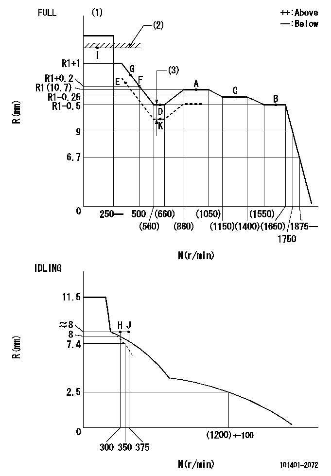
N:Pump speed
R:Rack position (mm)
(1)Torque cam stamping: T1
(2)RACK LIMIT
(3)Boost compensator stroke: BCL
----------
T1=C04 BCL=(1.2)+-0.1mm
----------
----------
T1=C04 BCL=(1.2)+-0.1mm
----------
Speed control lever angle

F:Full speed
I:Idle
(1)Stopper bolt setting
----------
----------
a=21.5deg+-5deg b=(43deg)+-3deg
----------
----------
a=21.5deg+-5deg b=(43deg)+-3deg
Stop lever angle

N:Pump normal
S:Stop the pump.
----------
----------
a=40deg+-5deg b=40deg+-5deg
----------
----------
a=40deg+-5deg b=40deg+-5deg
0000001501 ACTUATOR
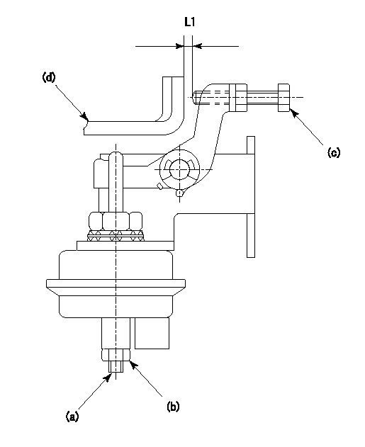
(a) Screw
(B) Nut
(c) set bolt
(d) control lever
1. Actuator adjustment procedure
(1)Position the control lever (d) in the idling position.
(2)Set the clearance between the control lever (d) and the set bolt (c) to approx. L1.
(3)Loosen the nut (b) and fully tighten the screw (a).
(4)Set the pump speed at N1and measure the rack position when negative pressure P1 is applied to the actuator.
(5)Loosen screw (a) and fix the nut (b) when the pump speed is N2 and the rack position is R1.
(6)Confirm that control lever (d) returns to the idling position at actuator negative pressure 0.
(7)Repeat procedures (4) to (6) several times and confirm that the control lever (d) moves smoothly.
----------
L1=2mm R1=9.1~9.4mm P1=66.7kPa(500mmHg) N1=300r/min N2=300r/min
----------
----------
L1=2mm R1=9.1~9.4mm P1=66.7kPa(500mmHg) N1=300r/min N2=300r/min
----------
Timing setting

(1)Pump vertical direction
(2)Position of gear's standard threaded hole at No 1 cylinder's beginning of injection
(3)-
(4)-
----------
----------
a=(70deg)
----------
----------
a=(70deg)
Information:
3. Install dowel (5) in governor shaft (6). Install the governor shaft in the carrier as shown. 4. Put the carrier in position on the camshaft. Install the bolts that hold the carrier in place.
Replace shield (7) with a new part any time it is removed.
5. Install shield (7) on the carrier, and use Tool (A) to push the shield against its seat. Use a hammer and punch to stake the metal in two places on the side of the shield 180° 5° apart next to the holes in the shield. 6. Install one race (9), bearing (10), the other race (9), and use Tool (B) to install the ring on riser (8) as shown. 7. Install riser (8) and the spring (overfueling spring) on the governor shaft as shown. 8. Assemble the dashpot as follows:a. Install spring (12) on seat (11). Install seat (13) in spring (12).b. Put spool (14) and ring (15) in position on seat (13). Use Tool (B) to install snap ring (16) to hold them in place. 9. Install dashpot assembly (17) on the governor shaft as shown. 10. Install ring (21) in the lower groove in the governor shaft. Install one sleeve (20), spring (19), the other sleeve (20) and bearing (18) on the governor shaft as shown. Spring (19) is used to put a preload on the thrust bearing on the camshaft in the fuel injection pump housing.11. Use Tool (C) to hold spring (19) under compression. Install ring (22) in the groove in the governor shaft. Remove Tool (C). 12. Put lever (27) in position on governor servo (23). Install pin (24) to hold the lever in place. Use a hammer and chisel to stake the metal four places 90° apart on the outside surface on both legs of the governor servo to hold pin (24) in place.13. Install the O-ring seal on sleeve (25). Install piston (26) and sleeve (25) in the governor servo as shown. 14. Install valve (28) in the governor servo as shown. 15. Install one lockring (32) in the groove near the center of valve (28). Put sleeve (29), spring (broken link spring) (30) and seat (31) in position on valve (28). Install the other lockring (32) to hold the components in place. 16. Put the governor servo in position on the fuel injection pump housing with piston (26) engaged over rack (33). Install the bolts that hold the governor servo in place. The 3306 Engine has two adjustment screws and lock nuts.17. Install torque rise adjustment screw (36) in collar (34) as shown. Install locknut (35) on the screw. 18. Install bolt (38) in block (40) as shown. Install spring (37) on bolt (38) as shown. Put collar (34) in position on bolt (38) with the hole in the collar