Information injection-pump assembly
ZEXEL
101401-2034
1014012034

Rating:
Cross reference number
ZEXEL
101401-2034
1014012034
Zexel num
Bosch num
Firm num
Name
101401-2034
INJECTION-PUMP ASSEMBLY
Calibration Data:
Adjustment conditions
Test oil
1404 Test oil ISO4113 or {SAEJ967d}
1404 Test oil ISO4113 or {SAEJ967d}
Test oil temperature
degC
40
40
45
Nozzle and nozzle holder
105780-8140
Bosch type code
EF8511/9A
Nozzle
105780-0000
Bosch type code
DN12SD12T
Nozzle holder
105780-2080
Bosch type code
EF8511/9
Opening pressure
MPa
17.2
Opening pressure
kgf/cm2
175
Injection pipe
Outer diameter - inner diameter - length (mm) mm 6-2-600
Outer diameter - inner diameter - length (mm) mm 6-2-600
Overflow valve
134424-0920
Overflow valve opening pressure
kPa
162
147
177
Overflow valve opening pressure
kgf/cm2
1.65
1.5
1.8
Tester oil delivery pressure
kPa
157
157
157
Tester oil delivery pressure
kgf/cm2
1.6
1.6
1.6
Direction of rotation (viewed from drive side)
Right R
Right R
Injection timing adjustment
Direction of rotation (viewed from drive side)
Right R
Right R
Injection order
1-3-4-2
Pre-stroke
mm
3.2
3.17
3.23
Beginning of injection position
Drive side NO.1
Drive side NO.1
Difference between angles 1
Cal 1-3 deg. 90 89.75 90.25
Cal 1-3 deg. 90 89.75 90.25
Difference between angles 2
Cal 1-4 deg. 180 179.75 180.25
Cal 1-4 deg. 180 179.75 180.25
Difference between angles 3
Cyl.1-2 deg. 270 269.75 270.25
Cyl.1-2 deg. 270 269.75 270.25
Injection quantity adjustment
Adjusting point
-
Rack position
10.7
Pump speed
r/min
900
900
900
Average injection quantity
mm3/st.
78.5
76.5
80.5
Max. variation between cylinders
%
0
-3
3
Basic
*
Fixing the rack
*
Standard for adjustment of the maximum variation between cylinders
*
Injection quantity adjustment_02
Adjusting point
H
Rack position
8+-0.5
Pump speed
r/min
300
300
300
Average injection quantity
mm3/st.
9
7.5
10.5
Max. variation between cylinders
%
0
-15
15
Fixing the rack
*
Standard for adjustment of the maximum variation between cylinders
*
Injection quantity adjustment_03
Adjusting point
A
Rack position
R1(10.7)
Pump speed
r/min
900
900
900
Average injection quantity
mm3/st.
78.5
77.5
79.5
Basic
*
Fixing the lever
*
Boost pressure
kPa
24
24
Boost pressure
mmHg
180
180
Injection quantity adjustment_04
Adjusting point
B
Rack position
R1-0.5
Pump speed
r/min
1600
1600
1600
Average injection quantity
mm3/st.
84.5
82.5
86.5
Fixing the lever
*
Boost pressure
kPa
24
24
Boost pressure
mmHg
180
180
Injection quantity adjustment_05
Adjusting point
C
Rack position
R1-0.25
Pump speed
r/min
1300
1300
1300
Average injection quantity
mm3/st.
82.3
78.3
86.3
Fixing the lever
*
Boost pressure
kPa
24
24
Boost pressure
mmHg
180
180
Injection quantity adjustment_06
Adjusting point
D
Rack position
R1-0.5
Pump speed
r/min
650
650
650
Average injection quantity
mm3/st.
62.7
58.7
66.7
Fixing the lever
*
Boost pressure
kPa
24
24
Boost pressure
mmHg
180
180
Injection quantity adjustment_07
Adjusting point
E
Rack position
-
Pump speed
r/min
400
400
400
Average injection quantity
mm3/st.
50
48
52
Fixing the lever
*
Boost pressure
kPa
0
0
0
Boost pressure
mmHg
0
0
0
Injection quantity adjustment_08
Adjusting point
I
Rack position
14.3+-0.
5
Pump speed
r/min
100
100
100
Average injection quantity
mm3/st.
110
110
120
Fixing the lever
*
Rack limit
*
Injection quantity adjustment_09
Adjusting point
K
Rack position
R2(9)
Pump speed
r/min
650
650
650
Average injection quantity
mm3/st.
39.3
35.3
43.3
Fixing the lever
*
Boost pressure
kPa
0
0
0
Boost pressure
mmHg
0
0
0
Boost compensator adjustment
Pump speed
r/min
650
650
650
Rack position
R2(9)
Boost pressure
kPa
2
2
4.7
Boost pressure
mmHg
15
15
35
Boost compensator adjustment_02
Pump speed
r/min
650
650
650
Rack position
R1-0.5
Boost pressure
kPa
10.7
10.7
10.7
Boost pressure
mmHg
80
80
80
Timer adjustment
Pump speed
r/min
1300+50
Advance angle
deg.
0
0
0
Remarks
Start
Start
Timer adjustment_02
Pump speed
r/min
1600
Advance angle
deg.
3.5
3.2
3.8
Remarks
Finish
Finish
Test data Ex:
Governor adjustment
N:Pump speed
R:Rack position (mm)
(1)Torque cam stamping: T1
(2)RACK LIMIT
(3)Boost compensator stroke: BCL
----------
T1=B31 BCL=(1.2)+-0.1mm
----------
----------
T1=B31 BCL=(1.2)+-0.1mm
----------
Speed control lever angle
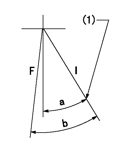
F:Full speed
I:Idle
(1)Stopper bolt set position 'H'
----------
----------
a=34deg+-5deg b=(43deg)+-3deg
----------
----------
a=34deg+-5deg b=(43deg)+-3deg
Stop lever angle

N:Pump normal
S:Stop the pump.
----------
----------
a=13deg+-5deg b=40deg+-5deg
----------
----------
a=13deg+-5deg b=40deg+-5deg
0000001501 ACTUATOR
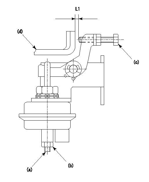
(a) Screw
(B) Nut
(c) set bolt
(d) control lever
1. Actuator adjustment procedure
(1)Position the control lever (d) in the idling position.
(2)Set the clearance between the control lever (d) and the set bolt (c) to approx. L1.
(3)Loosen the nut (b) and fully tighten the screw (a).
(4)Set the pump speed at N1and measure the rack position when negative pressure P1 is applied to the actuator.
(5)Loosen screw (a) and fix the nut (b) when the pump speed is N2 and the rack position is R1.
(6)Confirm that control lever (d) returns to the idling position at actuator negative pressure 0.
(7)Repeat procedures (4) to (6) several times and confirm that the control lever (d) moves smoothly.
----------
L1=2mm R1=9.1~9.4mm P1=66.7kPa(500mmHg) N1=300r/min N2=300r/min
----------
----------
L1=2mm R1=9.1~9.4mm P1=66.7kPa(500mmHg) N1=300r/min N2=300r/min
----------
Timing setting

(1)Pump vertical direction
(2)Position of gear's standard threaded hole at No 1 cylinder's beginning of injection
(3)-
(4)-
----------
----------
a=(70deg)
----------
----------
a=(70deg)
Information:
The information supplied in this service letter may not be valid after the termination date of this program. Do not perform the work outlined in this Service Letter after the termination date without first contacting your Caterpillar product analyst.
This Revised Service Letter replaces the October 20, 1993 Service Letter. Changes have been made to the Action Required.
Termination Date
January 31, 1994Problem
Certain 7N0449, 1W5829, 4W1819, 4W8483, 7W3710 and 1010060 Nozzle Assemblies need to be removed from Parts Stock because they may crack at the braze joint.
Action Required
Remove all 7N0449, 1W5829, 4W1819, 4W8483, 7W3710 and 1010060 Nozzle Assemblies from Parts Stock with a date code of D--3, E--3, F--3, or G--3. Refer to the Illustration below for the location of the date code. The date codes will appear as a letter followed by three numbers. The letter denotes the month, the first two numbers denote the day of the month, and the number 3 denotes the year. For example, D223 is the date code for April 22, 1993.
Location of Date CodeService Claim Allowances
Submit one claim for all 7N0449, 1W5829, 4W1819, 4W8483, 7W3710 and 1010060 Nozzle Assemblies removed from Parts Stock.
US and Canadian Dealers Only - When submitting a Parts Stock claim use 99Z00007 in the Product Identification Number Field.
Parts Disposition
U.S. and Canadian Dealers
Return all 7N0449, 1W5829, 4W1819, 4W8483, 7W3710 and 1010060 Nozzle Assemblies that are removed from Parts Stock and a copy of the claim to:
CaterpillarInc.
Attn:HowardJenkel/PI7324
Warehouse#4Docks7thru10
8201N.University
Peoria,IL 61615
All Other Dealers
Handle the parts in accordance with your Warranty Bulletin on warranty parts handling.
Have questions with 101401-2034?
Group cross 101401-2034 ZEXEL
Hino
101401-2034
INJECTION-PUMP ASSEMBLY