Information injection-pump assembly
ZEXEL
101401-2015
1014012015
HINO
220801246B
220801246b
Rating:
Service parts 101401-2015 INJECTION-PUMP ASSEMBLY:
1.
_
6.
COUPLING PLATE
7.
COUPLING PLATE
8.
_
9.
_
11.
Nozzle and Holder
12.
Open Pre:MPa(Kqf/cm2)
21.6(220)
15.
NOZZLE SET
Cross reference number
ZEXEL
101401-2015
1014012015
HINO
220801246B
220801246b
Zexel num
Bosch num
Firm num
Name
101401-2015
220801246B HINO
INJECTION-PUMP ASSEMBLY
W04C-T * K
W04C-T * K
Calibration Data:
Adjustment conditions
Test oil
1404 Test oil ISO4113 or {SAEJ967d}
1404 Test oil ISO4113 or {SAEJ967d}
Test oil temperature
degC
40
40
45
Nozzle and nozzle holder
105780-8140
Bosch type code
EF8511/9A
Nozzle
105780-0000
Bosch type code
DN12SD12T
Nozzle holder
105780-2080
Bosch type code
EF8511/9
Opening pressure
MPa
17.2
Opening pressure
kgf/cm2
175
Injection pipe
Outer diameter - inner diameter - length (mm) mm 6-2-600
Outer diameter - inner diameter - length (mm) mm 6-2-600
Overflow valve
134424-0920
Overflow valve opening pressure
kPa
162
147
177
Overflow valve opening pressure
kgf/cm2
1.65
1.5
1.8
Tester oil delivery pressure
kPa
157
157
157
Tester oil delivery pressure
kgf/cm2
1.6
1.6
1.6
Direction of rotation (viewed from drive side)
Right R
Right R
Injection timing adjustment
Direction of rotation (viewed from drive side)
Right R
Right R
Injection order
1-3-4-2
Pre-stroke
mm
3.2
3.17
3.23
Beginning of injection position
Drive side NO.1
Drive side NO.1
Difference between angles 1
Cal 1-3 deg. 90 89.75 90.25
Cal 1-3 deg. 90 89.75 90.25
Difference between angles 2
Cal 1-4 deg. 180 179.75 180.25
Cal 1-4 deg. 180 179.75 180.25
Difference between angles 3
Cyl.1-2 deg. 270 269.75 270.25
Cyl.1-2 deg. 270 269.75 270.25
Injection quantity adjustment
Adjusting point
-
Rack position
10.7
Pump speed
r/min
900
900
900
Average injection quantity
mm3/st.
78.5
76.5
80.5
Max. variation between cylinders
%
0
-3
3
Basic
*
Fixing the rack
*
Standard for adjustment of the maximum variation between cylinders
*
Injection quantity adjustment_02
Adjusting point
H
Rack position
8+-0.5
Pump speed
r/min
300
300
300
Average injection quantity
mm3/st.
9
7.5
10.5
Max. variation between cylinders
%
0
-15
15
Fixing the rack
*
Standard for adjustment of the maximum variation between cylinders
*
Injection quantity adjustment_03
Adjusting point
A
Rack position
R1(10.7)
Pump speed
r/min
900
900
900
Average injection quantity
mm3/st.
78.5
77.5
79.5
Basic
*
Fixing the lever
*
Boost pressure
kPa
24
24
Boost pressure
mmHg
180
180
Injection quantity adjustment_04
Adjusting point
B
Rack position
R1-0.5
Pump speed
r/min
1600
1600
1600
Average injection quantity
mm3/st.
84.5
82.5
86.5
Fixing the lever
*
Boost pressure
kPa
24
24
Boost pressure
mmHg
180
180
Injection quantity adjustment_05
Adjusting point
C
Rack position
R1-0.25
Pump speed
r/min
1300
1300
1300
Average injection quantity
mm3/st.
82.3
78.3
86.3
Fixing the lever
*
Boost pressure
kPa
24
24
Boost pressure
mmHg
180
180
Injection quantity adjustment_06
Adjusting point
D
Rack position
R1-0.5
Pump speed
r/min
650
650
650
Average injection quantity
mm3/st.
62.7
58.7
66.7
Fixing the lever
*
Boost pressure
kPa
24
24
Boost pressure
mmHg
180
180
Injection quantity adjustment_07
Adjusting point
E
Rack position
-
Pump speed
r/min
400
400
400
Average injection quantity
mm3/st.
50
48
52
Fixing the lever
*
Boost pressure
kPa
0
0
0
Boost pressure
mmHg
0
0
0
Injection quantity adjustment_08
Adjusting point
I
Rack position
-
Pump speed
r/min
100
100
100
Average injection quantity
mm3/st.
110
110
120
Fixing the lever
*
Rack limit
*
Injection quantity adjustment_09
Adjusting point
K
Rack position
R2(9)
Pump speed
r/min
650
650
650
Average injection quantity
mm3/st.
39.3
35.3
43.3
Fixing the lever
*
Boost pressure
kPa
0
0
0
Boost pressure
mmHg
0
0
0
Boost compensator adjustment
Pump speed
r/min
650
650
650
Rack position
R2(9)
Boost pressure
kPa
2
2
4.7
Boost pressure
mmHg
15
15
35
Boost compensator adjustment_02
Pump speed
r/min
650
650
650
Rack position
R1-0.5
Boost pressure
kPa
10.7
10.7
10.7
Boost pressure
mmHg
80
80
80
Timer adjustment
Pump speed
r/min
1300+50
Advance angle
deg.
0
0
0
Remarks
Start
Start
Timer adjustment_02
Pump speed
r/min
1600
Advance angle
deg.
3.5
3.2
3.8
Remarks
Finish
Finish
Test data Ex:
Governor adjustment
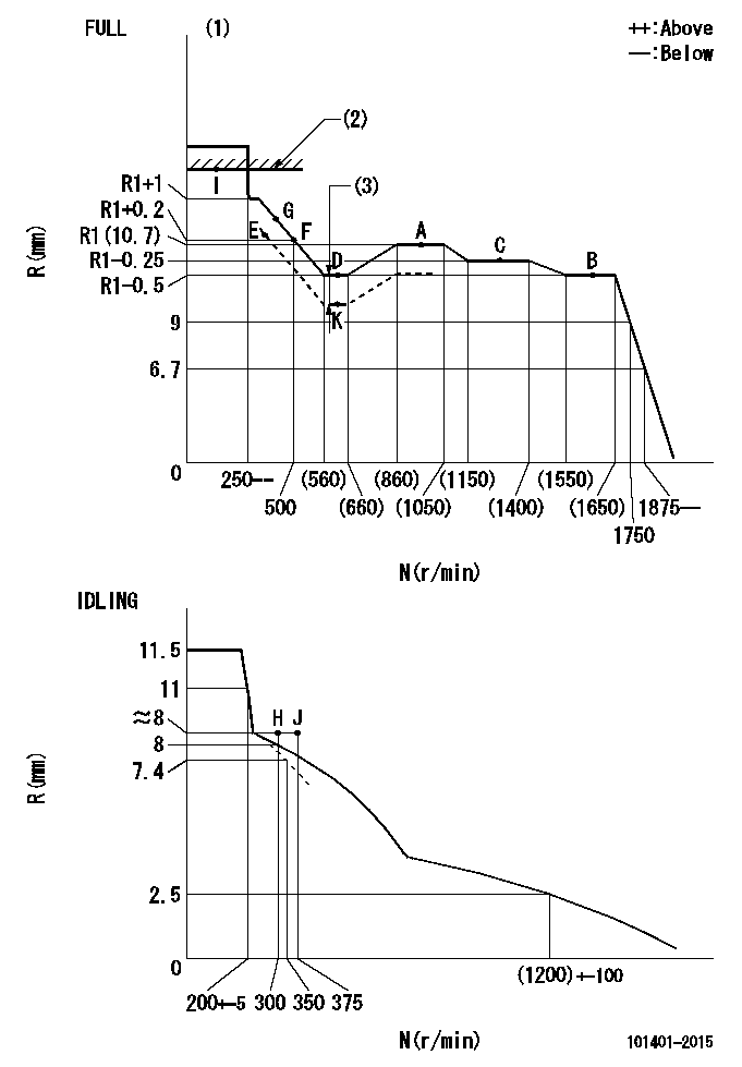
N:Pump speed
R:Rack position (mm)
(1)Torque cam stamping: T1
(2)RACK LIMIT
(3)Boost compensator stroke: BCL
----------
T1=B31 BCL=(1.2)+-0.1mm
----------
----------
T1=B31 BCL=(1.2)+-0.1mm
----------
Speed control lever angle

F:Full speed
I:Idle
(1)Stopper bolt set position 'H'
----------
----------
a=21.5deg+-5deg b=(43deg)+-3deg
----------
----------
a=21.5deg+-5deg b=(43deg)+-3deg
Stop lever angle

N:Pump normal
S:Stop the pump.
----------
----------
a=13deg+-5deg b=40deg+-5deg
----------
----------
a=13deg+-5deg b=40deg+-5deg
0000001501 ACTUATOR
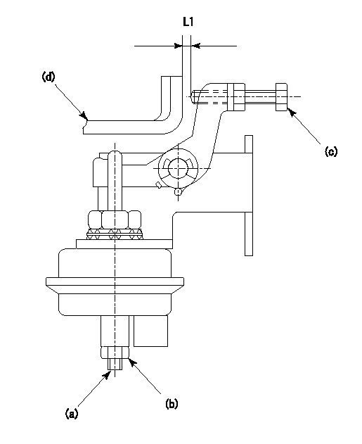
(a) Screw
(B) Nut
(c) set bolt
(d) control lever
1. Actuator adjustment procedure
(1)Position the control lever (d) in the idling position.
(2)Set the clearance between the control lever (d) and the set bolt (c) to approx. L1.
(3)Loosen the nut (b) and fully tighten the screw (a).
(4)Set the pump speed at N1and measure the rack position when negative pressure P1 is applied to the actuator.
(5)Loosen screw (a) and fix the nut (b) when the pump speed is N2 and the rack position is R1.
(6)Confirm that control lever (d) returns to the idling position at actuator negative pressure 0.
(7)Repeat procedures (4) to (6) several times and confirm that the control lever (d) moves smoothly.
----------
L1=2mm R1=9.1~9.4mm P1=66.7kPa(500mmHg) N1=300r/min N2=300r/min
----------
----------
L1=2mm R1=9.1~9.4mm P1=66.7kPa(500mmHg) N1=300r/min N2=300r/min
----------
Timing setting

(1)Pump vertical direction
(2)Position of gear's standard threaded hole at No 1 cylinder's beginning of injection
(3)-
(4)-
----------
----------
a=(70deg)
----------
----------
a=(70deg)
Information:
Problem
The fuel lines on certain D9N Tractors, 589 Pipelayers, 631E Tractors, 637E Tractors, 657E Scrapers, 768C Tractors, 769C Trucks, 834B Tractors, and 988B Loaders may fail. New fuel line groups can be installed that have a longer service life.
Affected Product
Model & Identification Number
Group 1
D9N (1JD1288, 1295, 1296, 1298-3280)
589 (31Z423-469)
631E (1AB965-1456; 1NB769-771)
637E TR (1FB361-537; 1JB612-724)
657E SC (90Z186-209; 91Z317-448)
768C (02X360-370)
769C (01X4394, 4403, 4418, 4420-5960)
Group 2
988B (50W08961, 50W8962, 50W8964-11257)
Group 3
834B (92Z368, 92Z370, 92Z373-512)
Parts Needed
Group 1
4 - 4B4274 Washer2 - 7C6525 Fuel Line Clamp2 - 7C6589 Fuel Line Clamp1 - 6I0030 Lines Group6 - 5M2894 Washer4 - 9N3388 Screw6 - 0S0509 BoltGroup 2
4 - 4B4274 Washer2 - 7C6525 Fuel Line Clamp2 - 7C6589 Fuel Line Clamp1 - 6I0030 Lines Group11 - 5M2894 Washer4 - 9N3388 Screw1 - 4P8261 Bracket1 - 4P8385 Bracket2 - 5P0537 Washer5 - 0S1571 Bolt6 - 0S0509 Bolt2 - 0S1615 Bolt3 - 8T1296 Washer1 - 1010462 RodGroup 3
4 - 4B4274 Washer2 - 7C6525 Fuel Line Clamp2 - 7C6589 Fuel Line Clamp1 - 1029884 Lines Group4 - 9N3388 Screw5 - 5M2894 Washer4 - 0S0509 Bolt1 - 0S1594 BoltAction Required
Parts Stock
Remove all 7C6931, 7C6932, 7C6933, 7C6934, 7C6935, 7C6936, 7C6937, and 7C6938 Fuel Lines from parts stock.
Affected Product
Remove the existing fuel lines and install the new fuel injection line groups as a group. Do not disassemble the fuel line groups and install them one line at a time. See the attached (pending) procedure.
Do not over tighten the screws of the metal-to-metal fuel line clamps. Use a 6V6069 Torque Screwdriver or similar tool to tighten the screw to a torque of 2.25 N m (20 lb.in.).
Service Claim Allowances
Parts Stock
Submit one claim for all 7C6931, 7C6932, 7C6933, 7C6934, 7C6935, 7C6936, 7C6937, and 7C6938 Fuel Lines removed from parts stock.
Affected Product
This is a 3-hour job.
Parts Disposition
Handle the parts in accordance with your Warranty Bulletin on warranty parts handling.
Attach. (1-Rework Procedure)Rework Procedure
Refer to the parts list and illustrations. Replace the existing fuel lines and their related parts with the new parts listed for each group.
To insure that the clamp locations are correct, install fuel line group as assembled. In a case where it is necessary to remove the clamps, mark their locations to insure correct positions when assembling.
1. Clean and paint the new 6I0030 or 102-9884 Fuel Line Group before proceeding to the job site. A) Install 5F2807 Plastic Caps and 2F2990 Plastic Plugs on the ends of the lines.B) Clean and paint the fuel line group.C) After drying, do not remove the plastic plugs and caps until the fuel line group is ready to be installed on the engine. Transport the fuel line group in it's original shipping box.2. Remove all mounting bolts from the fuel line brackets at the aftercooler housing. New mounting bolts and washers will be used. Keep the washers. The washers may be needed later as spacers.3. Remove the existing three line clamps from the 9Y4577 Bracket which is attached to the backside of the fuel injection pump (See Illustration 1). New 7C6525 Clamps, 7C6589 Clamps, 9N3388 Screws, and 4B4274 Washers
Have questions with 101401-2015?
Group cross 101401-2015 ZEXEL
Hino
Hino
101401-2015
220801246B
INJECTION-PUMP ASSEMBLY
W04C-T
W04C-T