Information injection-pump assembly
BOSCH
9 400 613 416
9400613416
ZEXEL
101401-1931
1014011931
Rating:
Include in #1:
101603-2300
as _
Cross reference number
BOSCH
9 400 613 416
9400613416
ZEXEL
101401-1931
1014011931
Zexel num
Bosch num
Firm num
Name
Calibration Data:
Adjustment conditions
Test oil
1404 Test oil ISO4113 or {SAEJ967d}
1404 Test oil ISO4113 or {SAEJ967d}
Test oil temperature
degC
40
40
45
Nozzle and nozzle holder
105780-8140
Bosch type code
EF8511/9A
Nozzle
105780-0000
Bosch type code
DN12SD12T
Nozzle holder
105780-2080
Bosch type code
EF8511/9
Opening pressure
MPa
17.2
Opening pressure
kgf/cm2
175
Injection pipe
Outer diameter - inner diameter - length (mm) mm 6-2-600
Outer diameter - inner diameter - length (mm) mm 6-2-600
Overflow valve
131424-4620
Overflow valve opening pressure
kPa
255
221
289
Overflow valve opening pressure
kgf/cm2
2.6
2.25
2.95
Tester oil delivery pressure
kPa
255
255
255
Tester oil delivery pressure
kgf/cm2
2.6
2.6
2.6
Direction of rotation (viewed from drive side)
Right R
Right R
Injection timing adjustment
Direction of rotation (viewed from drive side)
Right R
Right R
Injection order
1-3-4-2
Pre-stroke
mm
3.5
3.45
3.55
Beginning of injection position
Drive side NO.1
Drive side NO.1
Difference between angles 1
Cal 1-3 deg. 90 89.5 90.5
Cal 1-3 deg. 90 89.5 90.5
Difference between angles 2
Cal 1-4 deg. 180 179.5 180.5
Cal 1-4 deg. 180 179.5 180.5
Difference between angles 3
Cyl.1-2 deg. 270 269.5 270.5
Cyl.1-2 deg. 270 269.5 270.5
Injection quantity adjustment
Adjusting point
A
Rack position
10.4
Pump speed
r/min
1100
1100
1100
Average injection quantity
mm3/st.
96.5
95.5
97.5
Max. variation between cylinders
%
0
-2.5
2.5
Basic
*
Fixing the lever
*
Boost pressure
kPa
39.3
39.3
Boost pressure
mmHg
295
295
Injection quantity adjustment_02
Adjusting point
-
Rack position
7.7+-0.5
Pump speed
r/min
500
500
500
Average injection quantity
mm3/st.
8
6.7
9.3
Max. variation between cylinders
%
0
-14
14
Fixing the rack
*
Boost pressure
kPa
0
0
0
Boost pressure
mmHg
0
0
0
Remarks
Adjust only variation between cylinders; adjust governor according to governor specifications.
Adjust only variation between cylinders; adjust governor according to governor specifications.
Injection quantity adjustment_03
Adjusting point
C
Rack position
10.6++
Pump speed
r/min
100
100
100
Average injection quantity
mm3/st.
155
155
160
Fixing the lever
*
Boost pressure
kPa
0
0
0
Boost pressure
mmHg
0
0
0
Rack limit
*
Boost compensator adjustment
Pump speed
r/min
800
800
800
Rack position
R1-0.3
Boost pressure
kPa
13.3
6.6
20
Boost pressure
mmHg
100
50
150
Boost compensator adjustment_02
Pump speed
r/min
800
800
800
Rack position
R1(10.4)
Boost pressure
kPa
30
27.3
32.7
Boost pressure
mmHg
225
205
245
Timer adjustment
Pump speed
r/min
0
Advance angle
deg.
2.5
2
3
Timer adjustment_02
Pump speed
r/min
(630)
Advance angle
deg.
2.5
2
3
Remarks
Start
Start
Timer adjustment_03
Pump speed
r/min
720+-25
Advance angle
deg.
0
0
0
Remarks
Finish
Finish
Test data Ex:
Governor adjustment
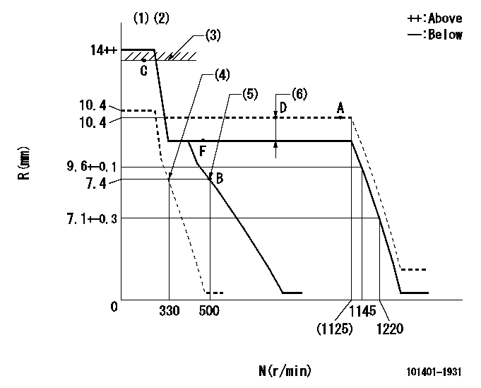
N:Pump speed
R:Rack position (mm)
(1)Target notch: K
(2)Tolerance for racks not indicated: +-0.05mm.
(3)RACK LIMIT
(4)Set idle sub-spring
(5)Main spring setting
(6)Boost compensator stroke: BCL
----------
K=10 BCL=0.3+-0.1mm
----------
----------
K=10 BCL=0.3+-0.1mm
----------
Speed control lever angle

F:Full speed
I:Idle
(1)Stopper bolt setting
----------
----------
a=(6deg)+-5deg b=(18deg)+-5deg
----------
----------
a=(6deg)+-5deg b=(18deg)+-5deg
Stop lever angle

N:Pump normal
S:Stop the pump.
(1)Pump speed aa and rack position bb (to be sealed at delivery)
(2)Normal
----------
aa=0r/min bb=1-0.5mm
----------
a=21deg+-5deg b=(55deg)
----------
aa=0r/min bb=1-0.5mm
----------
a=21deg+-5deg b=(55deg)
0000001501 TAMPER PROOF

Tamperproofing-equipped boost compensator cover installation procedure
(A) After adjusting the boost compensator, tighten the bolts to remove the heads.
(1)Before adjusting the governor and the boost compensator, tighten the screw to the specified torque.
(Tightening torque T = T1 maximum)
(2)After adjusting the governor and the boost compensator, tighten to the specified torque to break off the bolt heads.
(Tightening torque T = T2)
----------
T1=2.5N-m(0.25kgf-m) T2=2.9~4.4N-m(0.3~0.45kgf-m)
----------
----------
T1=2.5N-m(0.25kgf-m) T2=2.9~4.4N-m(0.3~0.45kgf-m)
----------
Timing setting

(1)Pump vertical direction
(2)Position of gear mark '3' at No 1 cylinder's beginning of injection
(3)B.T.D.C.: aa
(4)-
----------
aa=12deg
----------
a=(130deg)
----------
aa=12deg
----------
a=(130deg)
Information:
(1) Endplay for shaft (new) ... 0.102 0.025 mm (.004 .001 in) Maximum permissible endplay (worn) ... 0.20 mm (.008 in)(2) Thickness of thrust bearing (where thrust rings contact bearing) ... 5.36 0.03 mm (.211 .001 in)(3) Diameter of shaft (new) ... 12.697 to 12.705 mm (.4999 to .5002 in) Bore in the bearing (new) ... 12.741 to 12.748 mm (.5016 to .5019 in)Maximum permissible clearance between bearing and shaft (worn) ... 0.05 mm (.002 in)(4) Maximum permissible gap of oil seal ring, measured in bore of housing ... 0.25 mm (.010 in)
The impeller shaft nut is a left hand thread (CCW).
(5) Install the compressor wheel (at room temperature) as follows: a. Put compressor wheel on the shaft.b. Put a small amount of clean engine oil on the threads.c. Tighten the nut (CCW) to 14 to 17 N m (125 to 150 lb in).d. Loosen the nut and tighten again to 9 N m (80 lb in) plus an additional 60 degrees (1/6 turn).
Do not bend or add stress to the shaft when the nut is loosened or tightened.
(6) Thickness of each thrust ring ... 2.553 0.013 mm (.1005 .0005 in)(7) Bore in housing (new) ... 20.744 to 20.757 mm (.8167 to .8172 in) Outside diameter of the bearing (new) ... 20.630 to 20.643 mm (.8122 to .8127 in)Maximum permissible clearance between bearing and bore in housing (worn) ... 0.15 mm (.006 in)Torque for four nuts (put 5P3931 Anti-Seize Compound on threads) and bolts that hold turbocharger to exhaust manifold ... 55 5 N m (40 4 lb ft)Install the band clamps to hold the cartridge to the compressor housing as follows: a. Tighten clamps to 14 1.1 N m (125 10 lb in)b. Tap (hit) clamp lightly all around.c. Tighten again to ... 14 1.1 N m (125 10 lb in) Put clean engine oil in the oil inlet of the turbocharger after assembly or before installation to provide start up lubrication and/or storage protection.