Information injection-pump assembly
BOSCH
9 400 611 238
9400611238
ZEXEL
101401-1851
1014011851

Rating:
Service parts 101401-1851 INJECTION-PUMP ASSEMBLY:
1.
_
6.
COUPLING PLATE
7.
COUPLING PLATE
8.
_
9.
_
11.
Nozzle and Holder
ME016655
12.
Open Pre:MPa(Kqf/cm2)
21.6{220}
15.
NOZZLE SET
Cross reference number
BOSCH
9 400 611 238
9400611238
ZEXEL
101401-1851
1014011851
Zexel num
Bosch num
Firm num
Name
Calibration Data:
Adjustment conditions
Test oil
1404 Test oil ISO4113 or {SAEJ967d}
1404 Test oil ISO4113 or {SAEJ967d}
Test oil temperature
degC
40
40
45
Nozzle and nozzle holder
105780-8140
Bosch type code
EF8511/9A
Nozzle
105780-0000
Bosch type code
DN12SD12T
Nozzle holder
105780-2080
Bosch type code
EF8511/9
Opening pressure
MPa
17.2
Opening pressure
kgf/cm2
175
Injection pipe
Outer diameter - inner diameter - length (mm) mm 6-2-600
Outer diameter - inner diameter - length (mm) mm 6-2-600
Overflow valve
131424-4620
Overflow valve opening pressure
kPa
255
221
289
Overflow valve opening pressure
kgf/cm2
2.6
2.25
2.95
Tester oil delivery pressure
kPa
255
255
255
Tester oil delivery pressure
kgf/cm2
2.6
2.6
2.6
Direction of rotation (viewed from drive side)
Right R
Right R
Injection timing adjustment
Direction of rotation (viewed from drive side)
Right R
Right R
Injection order
1-3-4-2
Pre-stroke
mm
3.5
3.45
3.55
Beginning of injection position
Drive side NO.1
Drive side NO.1
Difference between angles 1
Cal 1-3 deg. 90 89.5 90.5
Cal 1-3 deg. 90 89.5 90.5
Difference between angles 2
Cal 1-4 deg. 180 179.5 180.5
Cal 1-4 deg. 180 179.5 180.5
Difference between angles 3
Cyl.1-2 deg. 270 269.5 270.5
Cyl.1-2 deg. 270 269.5 270.5
Injection quantity adjustment
Adjusting point
A
Rack position
9.7
Pump speed
r/min
1050
1050
1050
Average injection quantity
mm3/st.
76.5
75.5
77.5
Max. variation between cylinders
%
0
-2.5
2.5
Basic
*
Fixing the lever
*
Injection quantity adjustment_02
Adjusting point
B
Rack position
8+-0.5
Pump speed
r/min
400
400
400
Average injection quantity
mm3/st.
8.5
7.2
9.8
Max. variation between cylinders
%
0
-14
14
Fixing the rack
*
Injection quantity adjustment_03
Adjusting point
C
Rack position
-
Pump speed
r/min
100
100
100
Average injection quantity
mm3/st.
120
120
125
Fixing the lever
*
Rack limit
*
Timer adjustment
Pump speed
r/min
0
Advance angle
deg.
2.5
2
3
Timer adjustment_02
Pump speed
r/min
-
Advance angle
deg.
2.5
2
3
Remarks
Measure speed (beginning of operation).
Measure speed (beginning of operation).
Timer adjustment_03
Pump speed
r/min
-
Advance angle
deg.
0
0
0
Remarks
Measure the actual speed, stop
Measure the actual speed, stop
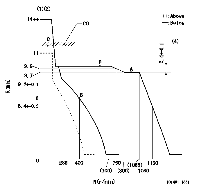
Test data Ex:
Governor adjustment

N:Pump speed
R:Rack position (mm)
(1)Target notch: K
(2)Tolerance for racks not indicated: +-0.05mm.
(3)RACK LIMIT
(4)Rack difference between N = N1 and N = N2
----------
K=14 N1=1050r/min N2=600r/min
----------
----------
K=14 N1=1050r/min N2=600r/min
----------
Speed control lever angle

F:Full speed
I:Idle
(1)Stopper bolt setting
----------
----------
a=7deg+-5deg b=22deg+-5deg
----------
----------
a=7deg+-5deg b=22deg+-5deg
Stop lever angle

N:Pump normal
S:Stop the pump.
(1)Normal
----------
----------
a=26.5deg+-5deg b=53deg+-5deg
----------
----------
a=26.5deg+-5deg b=53deg+-5deg
Timing setting

(1)Pump vertical direction
(2)Position of gear mark '3' at No 1 cylinder's beginning of injection
(3)B.T.D.C.: aa
(4)-
----------
aa=12deg
----------
a=(130deg)
----------
aa=12deg
----------
a=(130deg)
Information:
Turbocharger
Turbocharger
(1) Turbine wheel. (2) Compressor wheel. (3) Exhaust outlet. (4) Air inlet. (8) Oil inlet passage. (9) Oil outlet. (10) Exhaust inlet.The turbocharger is installed on the exhaust manifold. All the exhaust gases from the engine go through the turbocharger.The exhaust gases enter exhaust inlet (10) and go through the blades of turbine wheel (1), causing the turbine wheel and compressor wheel (2) to turn.When the compressor wheel turns, it pulls filtered air from the air cleaner through air inlet (4). The air is put in compression by action of the compressor wheel and is pushed to the inlet manifold of the engine.When engine load increases, more fuel is injected into the engine cylinders. The volume of exhaust gas increases, which causes the turbocharger turbine wheel and compressor wheel to turn faster. The increased rpm of the compressor wheel increases the quantity of inlet air. As the turbocharger provides additional inlet air, more fuel can be burned. This results in more horsepower from the engine at higher altitudes.Maximum rpm of the turbocharger is controlled by the high idle speed setting and the height above sea level at which the engine is operated.The bearings for the turbocharger use engine oil for lubrication. The oil comes in through oil inlet (8) and goes through passages in the center section for lubrication of the bearings. Oil from the turbocharger goes out through oil outlet (9) in the bottom of the center section and goes back to the engine oil pan.The turbocharger allows the engine to run properly at high altitudes where the air is leaner. In this application, the turbocharger does not give more power. It compensates for leaner air.Crankcase Ventilation System
The air intake system is also equipped with a crankcase ventilation system, or breather. The piston intake stroke pulls in atmospheric air to the crankcase area.
Crankcase Ventilation
(1) Ventilation hose. (2) Breather.The fumes in the crankcase flow through a passage of the engine block to the valve cover, through hose (1) and breather (2) to the atmosphere.Electrical System
The electrical system is a 12 volt, negative ground system that has two basic circuits. They are the starting circuit and the charging circuit, which includes the low amperage circuit with warning lights and gauges. Some of the electrical components are used in more than one circuit.The starting circuit is in operation only when the key start switch is turned to the START position. In the starting circuit, the transmission neutral/switch must be closed before the starter solenoid is energized (electrical energy).The charging circuit is in operation when the engine is running. The alternator in the charging circuit gives current to the electrical system. The battery keeps the storage of the current. A voltage regulator in the circuit, on the alternator housing, controls the amount of current output to the battery. The voltmeter in the circuit shows system voltage.Reference: For a complete electrical schematic, see Schematics For Backhoe Loader Electrical System, Form No. SENR3165; Backhoe Loader Electrical System (With Roading Arrangement), Form No. SENR3924;
