Information injection-pump assembly
ZEXEL
101401-1670
1014011670

Rating:
Cross reference number
ZEXEL
101401-1670
1014011670
Zexel num
Bosch num
Firm num
Name
101401-1670
INJECTION-PUMP ASSEMBLY
Calibration Data:
Adjustment conditions
Test oil
1404 Test oil ISO4113 or {SAEJ967d}
1404 Test oil ISO4113 or {SAEJ967d}
Test oil temperature
degC
40
40
45
Nozzle and nozzle holder
105780-8140
Bosch type code
EF8511/9A
Nozzle
105780-0000
Bosch type code
DN12SD12T
Nozzle holder
105780-2080
Bosch type code
EF8511/9
Opening pressure
MPa
17.2
Opening pressure
kgf/cm2
175
Injection pipe
Outer diameter - inner diameter - length (mm) mm 6-2-600
Outer diameter - inner diameter - length (mm) mm 6-2-600
Overflow valve
131424-8820
Overflow valve opening pressure
kPa
157
123
191
Overflow valve opening pressure
kgf/cm2
1.6
1.25
1.95
Tester oil delivery pressure
kPa
157
157
157
Tester oil delivery pressure
kgf/cm2
1.6
1.6
1.6
Direction of rotation (viewed from drive side)
Right R
Right R
Injection timing adjustment
Direction of rotation (viewed from drive side)
Right R
Right R
Injection order
1-3-4-2
Pre-stroke
mm
3.2
3.15
3.25
Beginning of injection position
Drive side NO.1
Drive side NO.1
Difference between angles 1
Cal 1-3 deg. 90 89.5 90.5
Cal 1-3 deg. 90 89.5 90.5
Difference between angles 2
Cal 1-4 deg. 180 179.5 180.5
Cal 1-4 deg. 180 179.5 180.5
Difference between angles 3
Cyl.1-2 deg. 270 269.5 270.5
Cyl.1-2 deg. 270 269.5 270.5
Injection quantity adjustment
Adjusting point
-
Rack position
11.1
Pump speed
r/min
900
900
900
Average injection quantity
mm3/st.
65
63.4
66.6
Max. variation between cylinders
%
0
-2.5
2.5
Basic
*
Fixing the rack
*
Standard for adjustment of the maximum variation between cylinders
*
Injection quantity adjustment_02
Adjusting point
H
Rack position
9.5+-0.5
Pump speed
r/min
325
325
325
Average injection quantity
mm3/st.
12
10.7
13.3
Max. variation between cylinders
%
0
-10
10
Fixing the rack
*
Standard for adjustment of the maximum variation between cylinders
*
Injection quantity adjustment_03
Adjusting point
A
Rack position
R1(11.1)
Pump speed
r/min
900
900
900
Average injection quantity
mm3/st.
65
64
66
Basic
*
Fixing the lever
*
Boost pressure
kPa
24
24
Boost pressure
mmHg
180
180
Injection quantity adjustment_04
Adjusting point
B
Rack position
R1+1.2
Pump speed
r/min
1600
1600
1600
Average injection quantity
mm3/st.
83.5
79.5
87.5
Fixing the lever
*
Boost pressure
kPa
24
24
Boost pressure
mmHg
180
180
Injection quantity adjustment_05
Adjusting point
C
Rack position
R1-0.4
Pump speed
r/min
600
600
600
Average injection quantity
mm3/st.
48.8
44.8
52.8
Fixing the lever
*
Boost pressure
kPa
24
24
Boost pressure
mmHg
180
180
Injection quantity adjustment_06
Adjusting point
D
Rack position
R2-0.2
Pump speed
r/min
300
300
300
Average injection quantity
mm3/st.
31.6
27.6
35.6
Fixing the lever
*
Boost pressure
kPa
0
0
0
Boost pressure
mmHg
0
0
0
Boost compensator adjustment
Pump speed
r/min
300
300
300
Rack position
R2-0.2
Boost pressure
kPa
5.3
4
6.6
Boost pressure
mmHg
40
30
50
Boost compensator adjustment_02
Pump speed
r/min
300
300
300
Rack position
R2(R1-0.
1)
Boost pressure
kPa
10.7
10.7
10.7
Boost pressure
mmHg
80
80
80
Timer adjustment
Pump speed
r/min
1250--
Advance angle
deg.
0
0
0
Remarks
Start
Start
Timer adjustment_02
Pump speed
r/min
1200
Advance angle
deg.
0.5
Timer adjustment_03
Pump speed
r/min
1600
Advance angle
deg.
2.5
2
3
Remarks
Finish
Finish
Test data Ex:
Governor adjustment
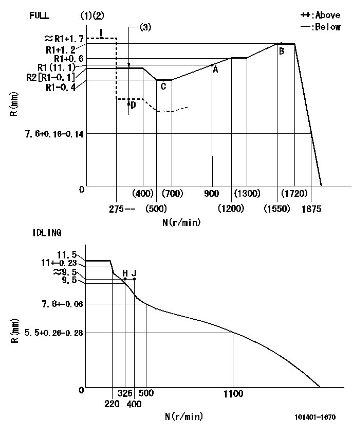
N:Pump speed
R:Rack position (mm)
(1)Torque cam stamping: T1
(2)Tolerance for racks not indicated: +-0.05mm.
(3)Boost compensator stroke: BCL
----------
T1=J10 BCL=0.2+-0.1mm
----------
----------
T1=J10 BCL=0.2+-0.1mm
----------
Speed control lever angle

F:Full speed
I:Idle
(1)Use the hole at R = aa
(2)Stopper bolt set position 'H'
----------
aa=40mm
----------
a=26deg+-5deg b=(40deg)+-3deg
----------
aa=40mm
----------
a=26deg+-5deg b=(40deg)+-3deg
Stop lever angle
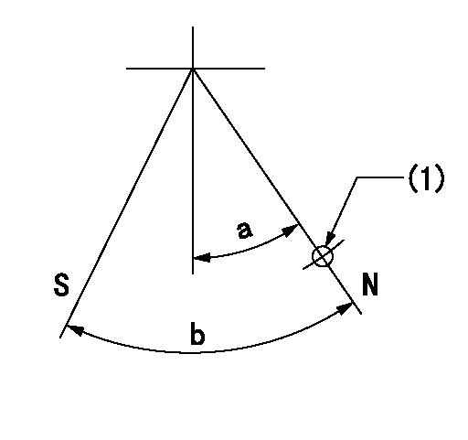
N:Pump normal
S:Stop the pump.
(1)Use the hole at R = aa
----------
aa=40mm
----------
a=33deg+-5deg b=40deg+-5deg
----------
aa=40mm
----------
a=33deg+-5deg b=40deg+-5deg
0000001501 MICRO SWITCH
Adjustment of the micro-switch
Adjust the bolt to obtain the following lever position when the micro-switch is ON.
(1)Speed N1
(2)Rack position Ra
----------
N1=1025r/min Ra=8.5+-0.1mm
----------
----------
N1=1025r/min Ra=8.5+-0.1mm
----------
Timing setting

(1)Pump vertical direction
(2)Position of gear mark '3' at No 1 cylinder's beginning of injection
(3)B.T.D.C.: aa
(4)-
----------
aa=10deg
----------
a=(130deg)
----------
aa=10deg
----------
a=(130deg)
Information:
The serial number of any injector(s) replaced in a machine covered under this service letter must be documented in the claims story. Only injectors with serial numbers between 11577640-11676551 (see action required for explanation on how to decode injector serial number) will be allowed to be claimed under this service letter.
If there has been a previous repair, part age will apply. Retain a copy of the previous repair in the dealer's records for audit purposes, and specify repair date and machine hours in the "Additional Comments" section of the warranty claim.
Product smu/age whichever comes first Caterpillar Dealer Suggested Customer Suggested
Parts % Labor Hrs% Parts % Labor Hrs% Parts % Labor Hrs%
*******Group 3*******
0-1000 hrs,
0-24 mo 100.0% 100.0% 0.0% 0.0% 0.0% 0.0%
This is a 4.0-hour job for Group 3
The serial number of any injector(s) replaced in a machine covered under this service letter must be documented in the claims story. Only injectors with serial numbers between 11577640-11676551 (see action required for explanation on how to decode injector serial number) will be allowed to be claimed under this service letter.
If there has been a previous repair, part age will apply. Retain a copy of the previous repair in the dealer's records for audit purposes, and specify repair date and machine hours in the "Additional Comments" section of the warranty claim.
Product smu/age whichever comes first Caterpillar Dealer Suggested Customer Suggested
Parts % Labor Hrs% Parts % Labor Hrs% Parts % Labor Hrs%
*******Group 4*******
0-1000 hrs,
0-24 mo 100.0% 100.0% 0.0% 0.0% 0.0% 0.0%
This is a 4.0-hour job for Group 4
The serial number of any injector(s) replaced in a machine covered under this service letter must be documented in the claims story. Only injectors with serial numbers between 11577640-11676551 (see action required for explanation on how to decode injector serial number) will be allowed to be claimed under this service letter.
If there has been a previous repair, part age will apply. Retain a copy of the previous repair in the dealer's records for audit purposes, and specify repair date and machine hours in the "Additional Comments" section of the warranty claim.
PARTS DISPOSITION
Handle the parts in accordance with your Warranty Bulletin on warranty parts handling.
Have questions with 101401-1670?
Group cross 101401-1670 ZEXEL
Mitsubishi
Mitsubishi
Mitsubishi
Mitsubishi
Mitsubishi
Mitsubishi
101401-1670
INJECTION-PUMP ASSEMBLY