Information injection-pump assembly
ZEXEL
101401-1083
1014011083

Rating:
Cross reference number
ZEXEL
101401-1083
1014011083
Zexel num
Bosch num
Firm num
Name
Calibration Data:
Adjustment conditions
Test oil
1404 Test oil ISO4113 or {SAEJ967d}
1404 Test oil ISO4113 or {SAEJ967d}
Test oil temperature
degC
40
40
45
Nozzle and nozzle holder
105780-8140
Bosch type code
EF8511/9A
Nozzle
105780-0000
Bosch type code
DN12SD12T
Nozzle holder
105780-2080
Bosch type code
EF8511/9
Opening pressure
MPa
17.2
Opening pressure
kgf/cm2
175
Injection pipe
Outer diameter - inner diameter - length (mm) mm 6-2-600
Outer diameter - inner diameter - length (mm) mm 6-2-600
Overflow valve
131424-6220
Overflow valve opening pressure
kPa
255
221
289
Overflow valve opening pressure
kgf/cm2
2.6
2.25
2.95
Tester oil delivery pressure
kPa
157
157
157
Tester oil delivery pressure
kgf/cm2
1.6
1.6
1.6
Direction of rotation (viewed from drive side)
Right R
Right R
Injection timing adjustment
Direction of rotation (viewed from drive side)
Right R
Right R
Injection order
1-3-4-2
Pre-stroke
mm
3.6
3.55
3.65
Beginning of injection position
Drive side NO.1
Drive side NO.1
Difference between angles 1
Cal 1-3 deg. 90 89.5 90.5
Cal 1-3 deg. 90 89.5 90.5
Difference between angles 2
Cal 1-4 deg. 180 179.5 180.5
Cal 1-4 deg. 180 179.5 180.5
Difference between angles 3
Cyl.1-2 deg. 270 269.5 270.5
Cyl.1-2 deg. 270 269.5 270.5
Injection quantity adjustment
Adjusting point
-
Rack position
10.6
Pump speed
r/min
1000
1000
1000
Average injection quantity
mm3/st.
53.1
52.1
54.1
Max. variation between cylinders
%
0
-2.5
2.5
Basic
*
Fixing the rack
*
Standard for adjustment of the maximum variation between cylinders
*
Injection quantity adjustment_02
Adjusting point
-
Rack position
9.7+-0.5
Pump speed
r/min
325
325
325
Average injection quantity
mm3/st.
10
8.7
11.3
Max. variation between cylinders
%
0
-10
10
Fixing the rack
*
Standard for adjustment of the maximum variation between cylinders
*
Remarks
Adjust only variation between cylinders; adjust governor according to governor specifications.
Adjust only variation between cylinders; adjust governor according to governor specifications.
Injection quantity adjustment_03
Adjusting point
A
Rack position
R1(10.6)
Pump speed
r/min
1000
1000
1000
Average injection quantity
mm3/st.
53.1
52.1
54.1
Basic
*
Fixing the lever
*
Boost pressure
kPa
42.7
42.7
Boost pressure
mmHg
320
320
Injection quantity adjustment_04
Adjusting point
B
Rack position
R1+0.6
Pump speed
r/min
1750
1750
1750
Average injection quantity
mm3/st.
72.7
68.7
76.7
Fixing the lever
*
Boost pressure
kPa
42.7
42.7
Boost pressure
mmHg
320
320
Injection quantity adjustment_05
Adjusting point
C
Rack position
R2(R1-0.
4)
Pump speed
r/min
700
700
700
Average injection quantity
mm3/st.
40.4
36.4
44.4
Fixing the lever
*
Boost pressure
kPa
0
0
0
Boost pressure
mmHg
0
0
0
Injection quantity adjustment_06
Adjusting point
D
Rack position
R2+0.7
Pump speed
r/min
500
500
500
Average injection quantity
mm3/st.
39.4
35.4
43.4
Fixing the lever
*
Boost pressure
kPa
0
0
0
Boost pressure
mmHg
0
0
0
Injection quantity adjustment_07
Adjusting point
I
Rack position
-
Pump speed
r/min
100
100
100
Average injection quantity
mm3/st.
67
67
72
Fixing the lever
*
Rack limit
*
Boost compensator adjustment
Pump speed
r/min
700
700
700
Rack position
R1-0.4
Boost pressure
kPa
22.7
22.7
22.7
Boost pressure
mmHg
170
170
170
Boost compensator adjustment_02
Pump speed
r/min
700
700
700
Rack position
R1-0.2
Boost pressure
kPa
27.3
26
28.6
Boost pressure
mmHg
205
195
215
Boost compensator adjustment_03
Pump speed
r/min
700
700
700
Rack position
R1(10.6)
Boost pressure
kPa
36
29.3
36
Boost pressure
mmHg
270
220
270
Timer adjustment
Pump speed
r/min
1450
Advance angle
deg.
0.3
Load
3/4
Timer adjustment_02
Pump speed
r/min
1700
Advance angle
deg.
3.5
3
4
Load
4/4
Remarks
Finish
Finish
Test data Ex:
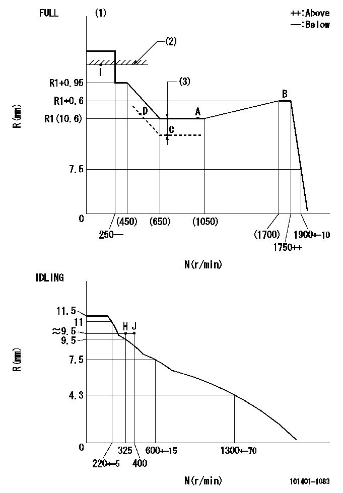
Governor adjustment

N:Pump speed
R:Rack position (mm)
(1)Torque cam stamping: T1
(2)RACK LIMIT
(3)Boost compensator stroke: BCL
----------
T1=C64 BCL=0.4+-0.1mm
----------
----------
T1=C64 BCL=0.4+-0.1mm
----------
Speed control lever angle

F:Full speed
I:Idle
(1)Use the hole at R = aa
(2)Stopper bolt set position 'H'
----------
aa=40mm
----------
a=26deg+-5deg b=42deg+-3deg
----------
aa=40mm
----------
a=26deg+-5deg b=42deg+-3deg
Stop lever angle

N:Engine manufacturer's normal use
S:Stop the pump.
(1)Free (at shipping)
(2)Use the hole at R = aa
(3)Rack position corresponding to bb
(4)Set the stopper bolt at speed = cc and rack position = dd.
(5)After setting the stopper bolt, confirm non-injection at speed ee. Rack position = ff or less.
----------
aa=40mm bb=16mm cc=1700r/min dd=6.5-0.5mm ee=325r/min ff=8mm
----------
a=8deg+-5deg b=15deg+-5deg c=25deg+-5deg
----------
aa=40mm bb=16mm cc=1700r/min dd=6.5-0.5mm ee=325r/min ff=8mm
----------
a=8deg+-5deg b=15deg+-5deg c=25deg+-5deg
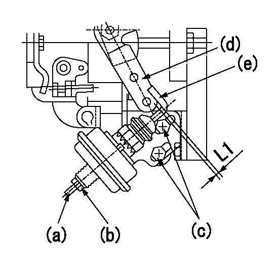
0000001501 ACTUATOR

(a) Screw
(B) Nut
Bolt c
(d) Speed lever
(e) Actuator shaft
1. Actuator adjustment procedure
(1)Position the speed lever (d) in the idle position.
(2)Set bolt (c) so that the clearance between the speed lever (d)'s pin and the actuator shaft (e) is approximately L1.
(3)Loosen the nut (b) and fully tighten the screw (a).
(4)Set the pump speed at N1 and read the rack position when negative pressure P1 is applied to the actuator.
(5)Gradually loosen screw (a) and fix the nut (b) when the pump speed is N2 and the rack position is R1.
(6)Apply negative pressure several times and confirm that the lever (d) returns to the idle position at negative pressure '0.'
(7)Confirm that rack position is R2 when negative pressure is P2.
----------
L1=2mm N1=500r/min P1=66.7kPa(500mmHg) N2=500r/min R1=9.1mm P2=66.7kPa(500mmHg) R2=9.1mm
----------
----------
L1=2mm N1=500r/min P1=66.7kPa(500mmHg) N2=500r/min R1=9.1mm P2=66.7kPa(500mmHg) R2=9.1mm
----------
Timing setting

(1)Pump vertical direction
(2)Position of gear mark '3' at No 1 cylinder's beginning of injection
(3)B.T.D.C.: aa
(4)-
----------
aa=11deg
----------
a=(130deg)
----------
aa=11deg
----------
a=(130deg)
Information:
Removing Connecting Rod and Piston
Removing Piston PinInspection
Inspect the removed parts. If any parts are found defective, replace or repair them.
Inspection of Piston and Connecting Rod1. Inspection of piston ring gapsPut each piston ring into the cylinder bore and push the ring with piston to position the ring on square with the cylinder wall. Measure the ring gap with a feeler gauge. If the measurement exceeds service limit, replace that piston ring.
Measuring Ring Gap CAUTION* When only the replacement of rings is to be made, without reboring (honing) of the cylinder, position the ring to be measured at the least worn place of cylinder skirt.* When replacing rings, install the new rings having the same size as the piston.* Piston rings available for servicing are sized into three classes: STD, 0.25 OS, and 0.50 OS.2. Inspection of ring groove in pistonMeasure the side clearance for each piston ring set in the ring groove in the piston. If the service limit is exceeded, replace the ring with new one. If the clearance still exceeds the service limit, replace the piston with new one.
Measuring Ring Side Clearance
Note: No. 1 ring is of the semi-key stone typeInstallation
When reassembling the piston and connecting rod and installing the piston-and-rod assemblies in the cylinder block, pay attention to the following:(1) Reassembling the piston and connecting rodUsing the Piston Pin Setting Tool, press the piston pin in to the set position.
Installation of Piston and Connecting Rod
Pressing in Piston Pin(2) Installation of piston rings
Installation of Piston Rings and Connecting Rod Cap(3) Set the piston ring gaps to the proper positions as shown in the figure at right. Coat the rings and cylinder wall with oil.
Proper Arrangement of Ring Gaps(4) Using a piston-ring compressor to compress the rings into the grooves, push the piston-and-rod assembly down into the cylinder. Be sure not to break the rings by excessively knocking the head of piston. Note that the front marks on the piston and connecting rod are toward the engine front.(5) Coat the bearing surface of the connecting rod caps with engine oil. Fit each cap to the connecting rod using match marks put before removal as a guide. In the case of a new rod which does not such a match mark, position the notches (provided for preventing the bearing from rotating) on the same side.
Fitting Cap to Connecting RodCRANKSHAFT
Construction
Crankshaft Component Parts(1) Key(2) Crankshaft(3) Crankshaft gear(4) Crankshaft pulley(5) Nut(6) Washer(7) Spring washer(8) Flywheel(9) Ring gear(10) Rear oil seal(11) Rear oil seal case(12) Gasket(13) Flywheel boltRemoval
(1) Loosen the flywheel bolts and remove the flywheel.(2) Loosen the crankshaft pulley nut and remove the pulley.(3) Remove the rear oil seal case assembly.(4) Remove the bearing caps. Keep each set of bearings removed together with its bearing cap.(5) Take out the crankshaft.
Removing Main Bearing CapInspection
Inspect the removed parts. If any parts are found defective, repair or replace them.
Inspection of Crankshaft and Flywheel1. Checking the crankshaft for wearTo check the crankpins and main journals for tapering wear and out-of-round wear, diameter of each crankpin