Information injection-pump assembly
ZEXEL
101401-0660
1014010660
ISUZU
8944081972
8944081972

Rating:
Cross reference number
ZEXEL
101401-0660
1014010660
ISUZU
8944081972
8944081972
Zexel num
Bosch num
Firm num
Name
Calibration Data:
Adjustment conditions
Test oil
1404 Test oil ISO4113 or {SAEJ967d}
1404 Test oil ISO4113 or {SAEJ967d}
Test oil temperature
degC
40
40
45
Nozzle and nozzle holder
105780-8140
Bosch type code
EF8511/9A
Nozzle
105780-0000
Bosch type code
DN12SD12T
Nozzle holder
105780-2080
Bosch type code
EF8511/9
Opening pressure
MPa
17.2
Opening pressure
kgf/cm2
175
Injection pipe
Outer diameter - inner diameter - length (mm) mm 6-2-600
Outer diameter - inner diameter - length (mm) mm 6-2-600
Overflow valve
131424-4920
Overflow valve opening pressure
kPa
127
107
147
Overflow valve opening pressure
kgf/cm2
1.3
1.1
1.5
Tester oil delivery pressure
kPa
157
157
157
Tester oil delivery pressure
kgf/cm2
1.6
1.6
1.6
Direction of rotation (viewed from drive side)
Right R
Right R
Injection timing adjustment
Direction of rotation (viewed from drive side)
Right R
Right R
Injection order
1-3-4-2
Pre-stroke
mm
3.4
3.35
3.45
Rack position
Point A R=A
Point A R=A
Beginning of injection position
Drive side NO.1
Drive side NO.1
Difference between angles 1
Cal 1-3 deg. 90 89.5 90.5
Cal 1-3 deg. 90 89.5 90.5
Difference between angles 2
Cal 1-4 deg. 180 179.5 180.5
Cal 1-4 deg. 180 179.5 180.5
Difference between angles 3
Cyl.1-2 deg. 270 269.5 270.5
Cyl.1-2 deg. 270 269.5 270.5
Injection quantity adjustment
Adjusting point
-
Rack position
11.2
Pump speed
r/min
900
900
900
Average injection quantity
mm3/st.
71.2
69.6
72.8
Max. variation between cylinders
%
0
-2.5
2.5
Basic
*
Fixing the rack
*
Standard for adjustment of the maximum variation between cylinders
*
Injection quantity adjustment_02
Adjusting point
-
Rack position
9.9+-0.5
Pump speed
r/min
290
290
290
Average injection quantity
mm3/st.
8
6.7
9.3
Max. variation between cylinders
%
0
-14
14
Fixing the rack
*
Standard for adjustment of the maximum variation between cylinders
*
Remarks
Adjust only variation between cylinders; adjust governor according to governor specifications.
Adjust only variation between cylinders; adjust governor according to governor specifications.
Injection quantity adjustment_03
Adjusting point
A
Rack position
R1(11.2)
Pump speed
r/min
900
900
900
Average injection quantity
mm3/st.
71.2
70.2
72.2
Basic
*
Fixing the lever
*
Boost pressure
kPa
14.7
14.7
Boost pressure
mmHg
110
110
Injection quantity adjustment_04
Adjusting point
I
Rack position
-
Pump speed
r/min
150
150
150
Average injection quantity
mm3/st.
90
90
Fixing the lever
*
Boost pressure
kPa
0
0
0
Boost pressure
mmHg
0
0
0
Boost compensator adjustment
Pump speed
r/min
550
550
550
Rack position
10.2
Boost pressure
kPa
2.7
2.7
5.4
Boost pressure
mmHg
20
20
40
Boost compensator adjustment_02
Pump speed
r/min
550
550
550
Rack position
10.7
Boost pressure
kPa
8
8
10.7
Boost pressure
mmHg
60
60
80
Boost compensator adjustment_03
Pump speed
r/min
550
550
550
Rack position
R1-0.25
Remarks
Measure actual boost pressure.
Measure actual boost pressure.
Timer adjustment
Pump speed
r/min
1250+-50
Advance angle
deg.
0
0
0
Remarks
Start
Start
Timer adjustment_02
Pump speed
r/min
1500
Advance angle
deg.
3.5
3
4
Remarks
Finish
Finish
Test data Ex:
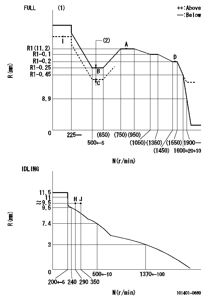
Governor adjustment

N:Pump speed
R:Rack position (mm)
(1)Torque cam stamping: T1
(2)Boost compensator stroke: BCL
----------
T1=A75 BCL=0.75+-0.1mm
----------
----------
T1=A75 BCL=0.75+-0.1mm
----------
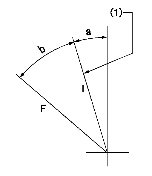
Speed control lever angle

F:Full speed
I:Idle
(1)Stopper bolt setting
----------
----------
a=5.5deg+-5deg b=32deg+-3deg
----------
----------
a=5.5deg+-5deg b=32deg+-3deg
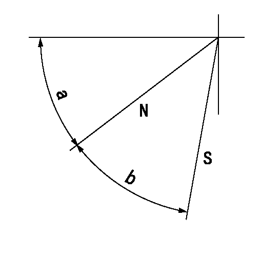
Stop lever angle

N:Pump normal
S:Stop the pump.
----------
----------
a=45deg+-5deg b=40deg+-5deg
----------
----------
a=45deg+-5deg b=40deg+-5deg
Timing setting

(1)Pump vertical direction
(2)Position of gear mark 'CC' at No 1 cylinder's beginning of injection
(3)B.T.D.C.: aa
(4)-
----------
aa=10deg
----------
a=(100deg)
----------
aa=10deg
----------
a=(100deg)
Information:
Fig. 5-Output TerminalStart engine and run at approximately 1500 rpm. Connect voltmeter negative lead to alternator ground terminal and connect positive lead to alternator auxiliary terminal (Fig. 4). Voltmeter should read 15.4 volts. Now move voltmeter positive lead to alternator output terminal (Fig. 5). Voltage reading should be 14.4 volts.If voltage at auxiliary terminal is 15.4 volts, while at the output terminal it is 12 volts or battery voltage, the isolation diode is open. Replace it. Test No. 4 - Field Draw Test (Key Switch Off)Detach regulator and let hang by red and black wires. DO NOT allow regulator to touch the output terminal. If test ammeter is not equipped with a 1/4-ohm resistor, a 1/4-ohm resistor should be connected in series with the ammeter to protect the meter.
Fig. 6-Field Terminal - Test 4Disconnect green field wire from field terminal. Connect ammeter from output terminal (2, Fig. 6) to field terminal (1). Current reading should be 2 to 2.5 amps. If less than this, check brushes and slip rings. Test No. 5 - Checking Alternator and Regulator With Regulator Disconnected (Key Switch On - Engine Running)Disconnect the regulator from the connector. Disconnect the green wire from the field terminal. Connect a jumper wire from the output terminal (2, Fig. 6) to the field terminal (1). Connect voltmeter negative lead to ground terminal and connect voltmeter positive lead to regulator terminal (3).Start engine and run at slow idle. This test isolates the defect to either the alternator or regulator.If voltage at regulator terminal rises to 15-16 volts now, when it did not with regulator connected in Test No. 3, then the regulator is defective and should be replaced.If voltage does not rise at regulator terminal and the field circuit was okay in Test No. 4, then the stator or rectifier diodes are defective. See Section 16, Group 1672 for testing diodes and stator. Test No. 6 - Alternator OutputIf not using JDST-23 tong-type ammeter, disconnect wire from alternator output terminal and connect ammeter from alternator output terminal 2, Fig. 6 to starter solenoid "Bat" terminal. Connect voltmeter negative lead to ground and connect positive lead to output terminal (2, Fig. 6). Connect a carbon pile resistor (turned off) to the battery.Run engine at approximately 1400 rpm. Use a master tachometer to measure rpm. Adjust carbon pile to obtain maximum alternator output at 13 to 15 volts. Ammeter should read 25 amps or more for the 35 amp alternator and 43 amps for the 55 amp alternator. Test No. 7 - Testing RegulatorThe regulator must be checked with an alternator that is in good condition. If the alternator is questionable, check it as previously instructed.Connect voltmeter with 0.1 volt accuracy to the alternator output terminal and ground terminal (Fig. 5). With charged batteries and the regulator brought to operating temperature (fifteen minutes operation), the voltage should be as specified for the surrounding air temperature. See chart below. If battery is partially discharged, it may be necessary to connect a