Information injection-pump assembly
ZEXEL
101401-0640
1014010640
ISUZU
8944077400
8944077400

Rating:
Service parts 101401-0640 INJECTION-PUMP ASSEMBLY:
1.
_
6.
COUPLING PLATE
7.
COUPLING PLATE
8.
_
9.
_
11.
Nozzle and Holder
5-15300-089-1
12.
Open Pre:MPa(Kqf/cm2)
18.1{185}
15.
NOZZLE SET
Cross reference number
ZEXEL
101401-0640
1014010640
ISUZU
8944077400
8944077400
Zexel num
Bosch num
Firm num
Name
Calibration Data:
Adjustment conditions
Test oil
1404 Test oil ISO4113 or {SAEJ967d}
1404 Test oil ISO4113 or {SAEJ967d}
Test oil temperature
degC
40
40
45
Nozzle and nozzle holder
105780-8140
Bosch type code
EF8511/9A
Nozzle
105780-0000
Bosch type code
DN12SD12T
Nozzle holder
105780-2080
Bosch type code
EF8511/9
Opening pressure
MPa
17.2
Opening pressure
kgf/cm2
175
Injection pipe
Outer diameter - inner diameter - length (mm) mm 6-2-600
Outer diameter - inner diameter - length (mm) mm 6-2-600
Overflow valve opening pressure
kPa
157
123
191
Overflow valve opening pressure
kgf/cm2
1.6
1.25
1.95
Tester oil delivery pressure
kPa
157
157
157
Tester oil delivery pressure
kgf/cm2
1.6
1.6
1.6
Direction of rotation (viewed from drive side)
Right R
Right R
Injection timing adjustment
Direction of rotation (viewed from drive side)
Right R
Right R
Injection order
1-3-4-2
Pre-stroke
mm
3.6
3.55
3.65
Beginning of injection position
Drive side NO.1
Drive side NO.1
Difference between angles 1
Cal 1-3 deg. 90 89.5 90.5
Cal 1-3 deg. 90 89.5 90.5
Difference between angles 2
Cal 1-4 deg. 180 179.5 180.5
Cal 1-4 deg. 180 179.5 180.5
Difference between angles 3
Cyl.1-2 deg. 270 269.5 270.5
Cyl.1-2 deg. 270 269.5 270.5
Injection quantity adjustment
Adjusting point
-
Rack position
11.2
Pump speed
r/min
950
950
950
Average injection quantity
mm3/st.
66.7
65.1
68.3
Max. variation between cylinders
%
0
-4
4
Basic
*
Fixing the rack
*
Standard for adjustment of the maximum variation between cylinders
*
Injection quantity adjustment_02
Adjusting point
H
Rack position
9.5+-0.5
Pump speed
r/min
290
290
290
Average injection quantity
mm3/st.
8
6.7
9.3
Max. variation between cylinders
%
0
-14
14
Fixing the rack
*
Standard for adjustment of the maximum variation between cylinders
*
Injection quantity adjustment_03
Adjusting point
A
Rack position
R1(11.2)
Pump speed
r/min
950
950
950
Average injection quantity
mm3/st.
66.7
65.7
67.7
Basic
*
Fixing the lever
*
Injection quantity adjustment_04
Adjusting point
B
Rack position
R1-0.4
Pump speed
r/min
1600
1600
1600
Average injection quantity
mm3/st.
63.3
60.1
66.5
Fixing the lever
*
Injection quantity adjustment_05
Adjusting point
C
Rack position
R1-0.1
Pump speed
r/min
1300
1300
1300
Average injection quantity
mm3/st.
70.7
67.5
73.9
Fixing the lever
*
Injection quantity adjustment_06
Adjusting point
D
Rack position
R1-0.25
Pump speed
r/min
650
650
650
Average injection quantity
mm3/st.
49.6
46.4
52.8
Fixing the lever
*
Injection quantity adjustment_07
Adjusting point
E
Rack position
R1+0.1
Pump speed
r/min
500
500
500
Average injection quantity
mm3/st.
49
45
53
Fixing the lever
*
Injection quantity adjustment_08
Adjusting point
I
Rack position
14.5+-0.
5
Pump speed
r/min
150
150
150
Average injection quantity
mm3/st.
95
95
103
Fixing the lever
*
Rack limit
*
Timer adjustment
Pump speed
r/min
1250
Advance angle
deg.
0.5
Timer adjustment_02
Pump speed
r/min
1350
Advance angle
deg.
1.1
Timer adjustment_03
Pump speed
r/min
1400
Advance angle
deg.
1.6
Timer adjustment_04
Pump speed
r/min
1600
Advance angle
deg.
5
4
5
Remarks
Finish
Finish
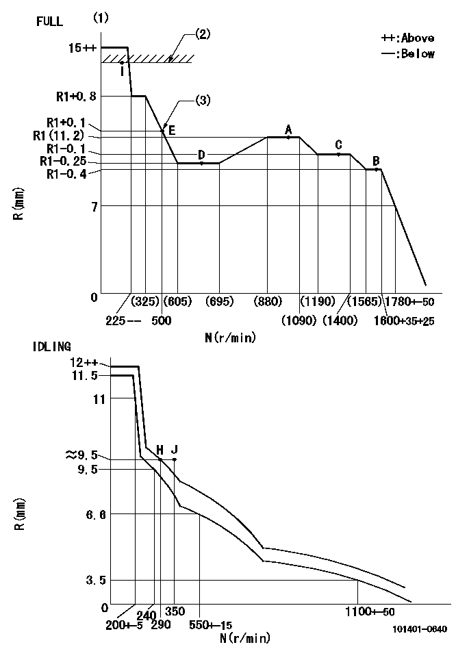
Test data Ex:
Governor adjustment

N:Pump speed
R:Rack position (mm)
(1)Torque cam stamping: T1
(2)RACK LIMIT: RAL
(3)Torque cam set point
----------
T1=47 RAL=(14.5)mm
----------
----------
T1=47 RAL=(14.5)mm
----------
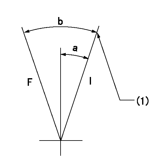
Speed control lever angle

F:Full speed
I:Idle
(1)Stopper bolt setting
----------
----------
a=30deg+-5deg b=41deg+-3deg
----------
----------
a=30deg+-5deg b=41deg+-3deg
Timing setting

(1)Pump vertical direction
(2)Position of gear mark 'CC' at No 1 cylinder's beginning of injection
(3)B.T.D.C.: aa
(4)-
----------
aa=13deg
----------
a=(100deg)
----------
aa=13deg
----------
a=(100deg)
Information:
Fan Belt
Removal
Fig. 1-Cap Screw and BoltLoosen cap screw and alternator mounting bolt (Fig. 1). Move alternator so fan belt can be moved off pulley. Remove fan belt.Repair
Inspect belts for:1 Cracking2 Rupture3 Tears4 Burning5 Gouging6 Wear7 Internal Cord Failure8 Cuts9 Peeling, Fraying, ChewingDo not reuse a damaged belt. Install a new belt.Installation
Fig. 2-Install Fan BeltPut fan belt over fan (1, Fig. 2). Put fan belt over crankshaft pulley (2) and alternator pulley (3). Position fan belt in pulley grooves.Adjust fan belt tension (Group 9010).Crankshaft Pulley
Removal
Remove fan belt from pulley (Group 0429).
Fig. 3-Cap Screw and WasherRemove cap screw and washer (Fig. 3) holding crankshaft pulley on crankshaft. IMPORTANT: On six cylinder engines the crankshaft pulley is also a vibration damper. Do not drop or hammer on vibration dampers.
Fig. 4-D01200AA PullerUsing D01200AA Puller (Fig. 4), pull crankshaft pulley off crankshaft.Repair
Inspect pulley sheaves for cracks and wear. Replace pulley if damaged.For vibration damper repair, see Group 0401.Installation
Position crankshaft pulley on crankshaft.Put washer on cap screw. Install cap screw through crankshaft pulley into crankshaft.
Fig. 5-Cap ScrewTighten cap screw (Fig. 5) to 85 lb-ft (115 N m) (12 kg-m).Install fan belts (Group 0429).Adjust fan belt tension (Group 9010).
Removal
Fig. 1-Cap Screw and BoltLoosen cap screw and alternator mounting bolt (Fig. 1). Move alternator so fan belt can be moved off pulley. Remove fan belt.Repair
Inspect belts for:1 Cracking2 Rupture3 Tears4 Burning5 Gouging6 Wear7 Internal Cord Failure8 Cuts9 Peeling, Fraying, ChewingDo not reuse a damaged belt. Install a new belt.Installation
Fig. 2-Install Fan BeltPut fan belt over fan (1, Fig. 2). Put fan belt over crankshaft pulley (2) and alternator pulley (3). Position fan belt in pulley grooves.Adjust fan belt tension (Group 9010).Crankshaft Pulley
Removal
Remove fan belt from pulley (Group 0429).
Fig. 3-Cap Screw and WasherRemove cap screw and washer (Fig. 3) holding crankshaft pulley on crankshaft. IMPORTANT: On six cylinder engines the crankshaft pulley is also a vibration damper. Do not drop or hammer on vibration dampers.
Fig. 4-D01200AA PullerUsing D01200AA Puller (Fig. 4), pull crankshaft pulley off crankshaft.Repair
Inspect pulley sheaves for cracks and wear. Replace pulley if damaged.For vibration damper repair, see Group 0401.Installation
Position crankshaft pulley on crankshaft.Put washer on cap screw. Install cap screw through crankshaft pulley into crankshaft.
Fig. 5-Cap ScrewTighten cap screw (Fig. 5) to 85 lb-ft (115 N m) (12 kg-m).Install fan belts (Group 0429).Adjust fan belt tension (Group 9010).
