Information injection-pump assembly
ZEXEL
101401-0630
1014010630
ISUZU
8941778730
8941778730

Rating:
Cross reference number
ZEXEL
101401-0630
1014010630
ISUZU
8941778730
8941778730
Zexel num
Bosch num
Firm num
Name
Calibration Data:
Adjustment conditions
Test oil
1404 Test oil ISO4113 or {SAEJ967d}
1404 Test oil ISO4113 or {SAEJ967d}
Test oil temperature
degC
40
40
45
Nozzle and nozzle holder
105780-8140
Bosch type code
EF8511/9A
Nozzle
105780-0000
Bosch type code
DN12SD12T
Nozzle holder
105780-2080
Bosch type code
EF8511/9
Opening pressure
MPa
17.2
Opening pressure
kgf/cm2
175
Injection pipe
Outer diameter - inner diameter - length (mm) mm 6-2-600
Outer diameter - inner diameter - length (mm) mm 6-2-600
Overflow valve
132424-0620
Overflow valve opening pressure
kPa
157
123
191
Overflow valve opening pressure
kgf/cm2
1.6
1.25
1.95
Tester oil delivery pressure
kPa
157
157
157
Tester oil delivery pressure
kgf/cm2
1.6
1.6
1.6
Direction of rotation (viewed from drive side)
Right R
Right R
Injection timing adjustment
Direction of rotation (viewed from drive side)
Right R
Right R
Injection order
1-3-4-2
Pre-stroke
mm
3.6
3.55
3.65
Rack position
Point A R=A
Point A R=A
Beginning of injection position
Drive side NO.1
Drive side NO.1
Difference between angles 1
Cal 1-3 deg. 90 89.5 90.5
Cal 1-3 deg. 90 89.5 90.5
Difference between angles 2
Cal 1-4 deg. 180 179.5 180.5
Cal 1-4 deg. 180 179.5 180.5
Difference between angles 3
Cyl.1-2 deg. 270 269.5 270.5
Cyl.1-2 deg. 270 269.5 270.5
Injection quantity adjustment
Adjusting point
-
Rack position
17.3
Pump speed
r/min
950
950
950
Average injection quantity
mm3/st.
55.4
53.8
57
Max. variation between cylinders
%
0
-2.5
2.5
Basic
*
Fixing the rack
*
Standard for adjustment of the maximum variation between cylinders
*
Injection quantity adjustment_02
Adjusting point
H
Rack position
9.5+-0.5
Pump speed
r/min
325
325
325
Average injection quantity
mm3/st.
13.2
11.9
14.5
Max. variation between cylinders
%
0
-14
14
Fixing the rack
*
Standard for adjustment of the maximum variation between cylinders
*
Injection quantity adjustment_03
Adjusting point
A
Rack position
R1(12.3)
Pump speed
r/min
950
950
950
Average injection quantity
mm3/st.
55.4
54.4
56.4
Basic
*
Fixing the lever
*
Injection quantity adjustment_04
Adjusting point
B
Rack position
R1-0.55
Pump speed
r/min
1600
1600
1600
Average injection quantity
mm3/st.
54
50.8
57.2
Fixing the lever
*
Injection quantity adjustment_05
Adjusting point
C
Rack position
R1-0.45
Pump speed
r/min
1300
1300
1300
Average injection quantity
mm3/st.
54
50.8
57.2
Fixing the lever
*
Injection quantity adjustment_06
Adjusting point
D
Rack position
R1(12.3)
Pump speed
r/min
650
650
650
Average injection quantity
mm3/st.
43
39.8
46.2
Fixing the lever
*
Injection quantity adjustment_07
Adjusting point
E
Rack position
R1+0.9
Pump speed
r/min
500
500
500
Average injection quantity
mm3/st.
46.5
42.5
50.5
Fixing the lever
*
Injection quantity adjustment_08
Adjusting point
I
Rack position
R2
Pump speed
r/min
150
150
150
Average injection quantity
mm3/st.
79
79
87
Fixing the lever
*
Rack limit
*
Timer adjustment
Pump speed
r/min
1050+-50
Advance angle
deg.
0
0
0
Remarks
Start
Start
Timer adjustment_02
Pump speed
r/min
1600
Advance angle
deg.
3
2.5
3.5
Remarks
Finish
Finish
Test data Ex:
Governor adjustment

N:Pump speed
R:Rack position (mm)
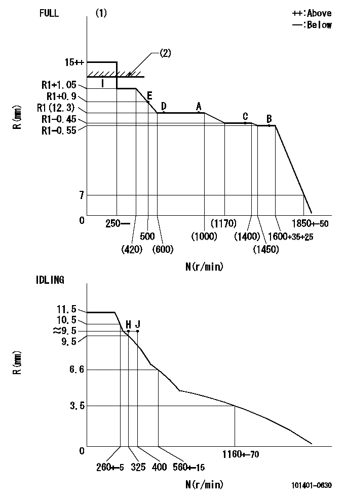
(1)Torque cam stamping: T1
(2)RACK LIMIT
----------
T1=B00
----------
----------
T1=B00
----------
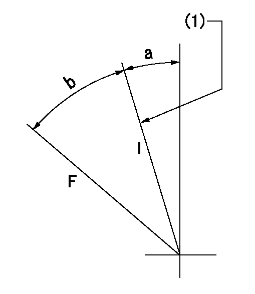
Speed control lever angle

F:Full speed
I:Idle
(1)Stopper bolt set position 'H'
----------
----------
a=2.5deg+-5deg b=(42deg)+-3deg
----------
----------
a=2.5deg+-5deg b=(42deg)+-3deg
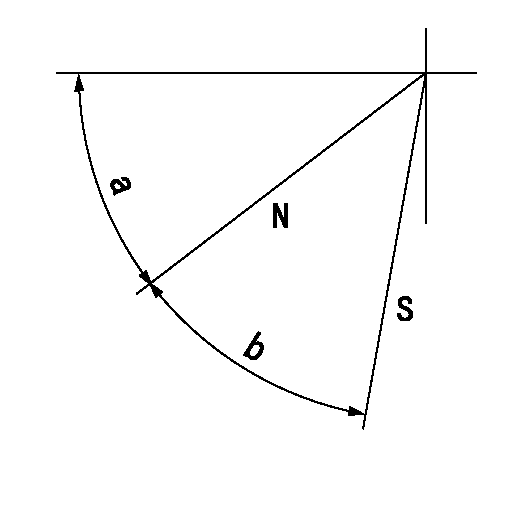
Stop lever angle

N:Pump normal
S:Stop the pump.
----------
----------
a=45deg+-5deg b=40deg+-5deg
----------
----------
a=45deg+-5deg b=40deg+-5deg
Timing setting

(1)Pump vertical direction
(2)Position of gear mark 'CC' at No 1 cylinder's beginning of injection
(3)B.T.D.C.: aa
(4)-
----------
aa=14deg
----------
a=(100deg)
----------
aa=14deg
----------
a=(100deg)
Information:
General Information
Fig. 1-Fuel Pump LocationThe fuel transfer pump is located on the right side of the engine as shown on (1, Fig. 1).Removal
Disconnect and plug fuel lines (2, Fig. 1) at pump.Remove attaching hardware.Repair
Airtex Fuel Transfer Pumps
Fig. 2-Airtex Fuel Transfer PumpTo remove or install primer lever, (1, Fig. 2) compress rocker arm lever (2). And pull primer lever out.Further disassembly of the transfer pump is not possible.A.C. Fuel Transfer Pumps
When disassembling, mark pump cover and pump body for easier reassembly.Test all parts for serviceability and replace, if necessary.When assembling the fuel pump, observe the following:
Fig. 3-A.C. Fuel Transfer PumpMake sure diaphragm (1, Fig. 3) is engaged in rocker arm (2).Before installing the pump cover (3), position diaphragm so that it is level by moving rocker arm. Hold lever in this position.Install pump cover and cover screws. However, turn in screws so that they just contact the washers. Operate rocker arm several times, then release with a snap to make sure that diaphragm will not be overstretched when in use. Tighten cover screws in a crosswise pattern.Corona (B.C.D.) Fuel Transfer Pump
When disassembling, mark pump cover and pump body for easier reassembly.
Fig. 4-Diaphragm RemovalDisconnect diaphragm by pressing it against flange (Fig. 4).
Fig. 5-Remove Valve Plate and FilterCarefully remove valve plate with filter from pump cover (Fig. 5).Check all parts for serviceability and replace, if necessary.When assembling the fuel pump, observe the following: Make sure diaphragm is engaged in rocker arm.Before installing the pump cover, position diaphragm so that it is level by moving rocker arm. Hold lever in this position.Install pump cover and cover screws. However, turn in screws so that they just contact the washers.Operate rocker arm several times, then release with a snap to make sure that diaphragm will not be overstretched when in use.Tighten cover screws in a crosswise pattern.Installation
Using a new gasket, attach transfer pump to cylinder block. Connect lines and bleed fuel system.