Information injection-pump assembly
ZEXEL
101401-0610
1014010610

Rating:
Cross reference number
ZEXEL
101401-0610
1014010610
Zexel num
Bosch num
Firm num
Name
Calibration Data:
Adjustment conditions
Test oil
1404 Test oil ISO4113 or {SAEJ967d}
1404 Test oil ISO4113 or {SAEJ967d}
Test oil temperature
degC
40
40
45
Nozzle and nozzle holder
105780-8140
Bosch type code
EF8511/9A
Nozzle
105780-0000
Bosch type code
DN12SD12T
Nozzle holder
105780-2080
Bosch type code
EF8511/9
Opening pressure
MPa
17.2
Opening pressure
kgf/cm2
175
Injection pipe
Outer diameter - inner diameter - length (mm) mm 6-2-600
Outer diameter - inner diameter - length (mm) mm 6-2-600
Overflow valve
131424-4920
Overflow valve opening pressure
kPa
127
107
147
Overflow valve opening pressure
kgf/cm2
1.3
1.1
1.5
Tester oil delivery pressure
kPa
157
157
157
Tester oil delivery pressure
kgf/cm2
1.6
1.6
1.6
Direction of rotation (viewed from drive side)
Right R
Right R
Injection timing adjustment
Direction of rotation (viewed from drive side)
Right R
Right R
Injection order
1-3-4-2
Pre-stroke
mm
3.4
3.35
3.45
Beginning of injection position
Drive side NO.1
Drive side NO.1
Difference between angles 1
Cal 1-3 deg. 90 89.5 90.5
Cal 1-3 deg. 90 89.5 90.5
Difference between angles 2
Cal 1-4 deg. 180 179.5 180.5
Cal 1-4 deg. 180 179.5 180.5
Difference between angles 3
Cyl.1-2 deg. 270 269.5 270.5
Cyl.1-2 deg. 270 269.5 270.5
Injection quantity adjustment
Adjusting point
-
Rack position
12.3
Pump speed
r/min
950
950
950
Average injection quantity
mm3/st.
74.5
72.9
76.1
Max. variation between cylinders
%
0
-2.5
2.5
Basic
*
Fixing the rack
*
Standard for adjustment of the maximum variation between cylinders
*
Injection quantity adjustment_02
Adjusting point
-
Rack position
9.6+-0.5
Pump speed
r/min
300
300
300
Average injection quantity
mm3/st.
8
6.7
9.3
Max. variation between cylinders
%
0
-14
14
Fixing the rack
*
Standard for adjustment of the maximum variation between cylinders
*
Remarks
Adjust only variation between cylinders; adjust governor according to governor specifications.
Adjust only variation between cylinders; adjust governor according to governor specifications.
Injection quantity adjustment_03
Adjusting point
A
Rack position
R1(12.3)
Pump speed
r/min
950
950
950
Average injection quantity
mm3/st.
74.5
73.5
75.5
Basic
*
Fixing the lever
*
Injection quantity adjustment_04
Adjusting point
I
Rack position
14.4+-0.
5
Pump speed
r/min
150
150
150
Average injection quantity
mm3/st.
79
79
87
Fixing the lever
*
Rack limit
*
Timer adjustment
Pump speed
r/min
1000+-50
Advance angle
deg.
0
0
0
Remarks
Start
Start
Timer adjustment_02
Pump speed
r/min
1600
Advance angle
deg.
2
1.5
2.5
Remarks
Finish
Finish
Test data Ex:
Governor adjustment

N:Pump speed
R:Rack position (mm)
(1)Torque cam stamping: T1
(2)RACK LIMIT
----------
T1=B19
----------
----------
T1=B19
----------
Speed control lever angle

F:Full speed
I:Idle
(1)Stopper bolt set position 'H'
----------
----------
a=2.5deg+-5deg b=32deg+-3deg
----------
----------
a=2.5deg+-5deg b=32deg+-3deg
Stop lever angle
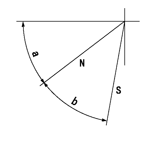
N:Pump normal
S:Stop the pump.
----------
----------
a=45deg+-5deg b=40deg+-5deg
----------
----------
a=45deg+-5deg b=40deg+-5deg
0000001501 ACS

(A) Set screw
(B) Push rod 1
(C) Push rod 2
(D) Cover
1. Aneroid compensator unit adjustment
(1)Select the push rod 2 to obtain L2.
(2)Screw in (A) to obtain L1.
2. Adjustment when mounting the governor.
(1)Set the speed of the pump to N1 r/min and fix the control lever at the full set position.
(2)Screw in the aneroid compensator to obtain the performance shown in the graph above.
(3)As there is hysterisis, measure when the absolute pressure drops.
(4)Hysterisis must not exceed rack position = h1.
----------
N1=950r/min L1=(1.5)mm L2=11+-0.5mm h1=0.15mm
----------
Ra=R1(12.3)mm Rb=(R1-0.3)mm Pa=89.8+-2.7kPa(674+-20mmHg) Pb=70.1+-0.7kPa(526+-5mmHg) Q1=74.5+-1cm3/1000st Q2=71+-1.5cm3/1000st
----------
N1=950r/min L1=(1.5)mm L2=11+-0.5mm h1=0.15mm
----------
Ra=R1(12.3)mm Rb=(R1-0.3)mm Pa=89.8+-2.7kPa(674+-20mmHg) Pb=70.1+-0.7kPa(526+-5mmHg) Q1=74.5+-1cm3/1000st Q2=71+-1.5cm3/1000st
Timing setting

(1)Pump vertical direction
(2)Position of gear mark 'CC' at No 1 cylinder's beginning of injection
(3)B.T.D.C.: aa
(4)-
----------
aa=14deg
----------
a=(100deg)
----------
aa=14deg
----------
a=(100deg)
Information:
Fig. 37-Injection Line to Injection Pump Screw TorqueConnect injection lines to injection pump using NEW washers (Fig. 37).Injection line to injection pump screw torque ... 35 lb-ft(47 N m)
Fig. 38-Fuel Supply and Return LinesConnect fuel supply line (1, Fig. 38) and fuel return line (2).Fuel supply line connection torque (1) ... 20 lb-ft(27 N m)Fuel return line connection torque (2) ... 20 lb-ft(27 N m)Connect throttle linkage, remove timing window, and install timing hole cover.Bleed the fuel system (Group 0413).See Group 9010 for adjustments.4-239T, 4-276T, 6-359T, 6-414D or 6-414T Engine
Position number one piston at top dead center on compression stroke.
Fig. 39-19918 Timing WindowRemove timing hole cover and install 19918 Timing Window (Fig. 39) on injection pump.Check pump mounting flange packing for damage or wear. Replace if necessary.
Fig. 40-Injection Pump Timing LinesRotate pump drive shaft and align timing lines (Fig. 40) on governor weight retainer and cam ring.Position pump on engine front plate making sure Woodruff key enters drive gear.
Fig. 41-Injection Pump Drive Gear NutInstall washer and nut on oiled pump drive shaft (Fig. 41).Injection pump drive gear nut torque (oiled) ... 150 lb-ft(203 N m)
Fig. 42-Injection Pump Attaching NutsInstall pump attaching nuts (Fig. 42) finger tight.Rotate injection pump housing counterclockwise (viewed from flywheel end) as far as possible.Rotate crankshaft counterclockwise (viewed from front end) approximately 180°. Reverse rotation and reposition number one piston at top dead center on compression stroke.Rotate injection pump housing clockwise (viewed from flywheel end) until timing lines align.Tighten injection pump attaching nuts (Fig. 42).Injection pump attaching nut torque ... 20 lb-ft(27 N m)Rotate crankshaft counterclockwise (viewed from front end) approximately 180°. Reverse rotation and reposition number one piston at top dead center on compression stroke.Injection pump timing lines should be aligned. If not, retime injection pump.
Fig. 43-Fuel Supply and Return LinesConnect fuel supply line (1, Fig. 43), fuel return line (2) and fuel injection lines (3).Fuel line connection torque (1) ... 20 lb-ft(27 N m)Fuel return line ... 20 lb-ft(27 N m)Fuel injection line connector torque ... 20 lb-ft(27 N m)Connect throttle linkage, remove timing window, and install timing hole cover.Bleed the fuel system (Group 0413).See Group 9010 for adjustments.Bleeding
Fig. 44-Fuel Filter Bleed ScrewLoosen fuel filter bleed screw (Fig. 44).
Fig. 45-Fuel Transfer Pump Primer LeverPump primer lever (Fig. 45), located on fuel transfer pump, until no air flows from bleed screw.Tighten the bleed screw.All Engines Except 3-179D
Fig. 46-Fuel Supply Line ConnectionSlightly crack fuel supply line connection at injection pump (Fig. 46) and pump primer lever until no air flows from fuel supply line connection.Tighten fuel supply line connection to 20 lb-ft (27 N m).Leave primer lever positioned toward the cylinder block.Loosen each nozzle inlet connector and turn engine until fuel flows form connector.Tighten nozzle inlet connector to 35 lb-ft (47 N m).3-179D Engine
If engine will not start after bleeding fuel filter, bleed fuel injection pump as follows:
Fig. 47-Roto-Diesel Fuel Injection Pump Bleed ScrewsLoosen lower bleed screw (B, Fig. 47).Pump primer lever on fuel transfer pump until fuel