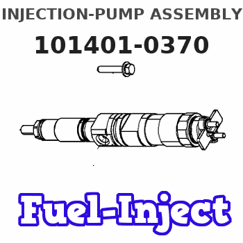
Information injection-pump assembly
ZEXEL
101401-0370
1014010370
ISUZU
8941310090
8941310090
Rating:
Cross reference number
ZEXEL
101401-0370
1014010370
ISUZU
8941310090
8941310090
Zexel num
Bosch num
Firm num
Name
Calibration Data:
Adjustment conditions
Test oil
1404 Test oil ISO4113 or {SAEJ967d}
1404 Test oil ISO4113 or {SAEJ967d}
Test oil temperature
degC
40
40
45
Nozzle and nozzle holder
105780-8140
Bosch type code
EF8511/9A
Nozzle
105780-0000
Bosch type code
DN12SD12T
Nozzle holder
105780-2080
Bosch type code
EF8511/9
Opening pressure
MPa
17.2
Opening pressure
kgf/cm2
175
Injection pipe
Outer diameter - inner diameter - length (mm) mm 6-2-600
Outer diameter - inner diameter - length (mm) mm 6-2-600
Overflow valve
131424-4920
Overflow valve opening pressure
kPa
127
107
147
Overflow valve opening pressure
kgf/cm2
1.3
1.1
1.5
Tester oil delivery pressure
kPa
157
157
157
Tester oil delivery pressure
kgf/cm2
1.6
1.6
1.6
Direction of rotation (viewed from drive side)
Right R
Right R
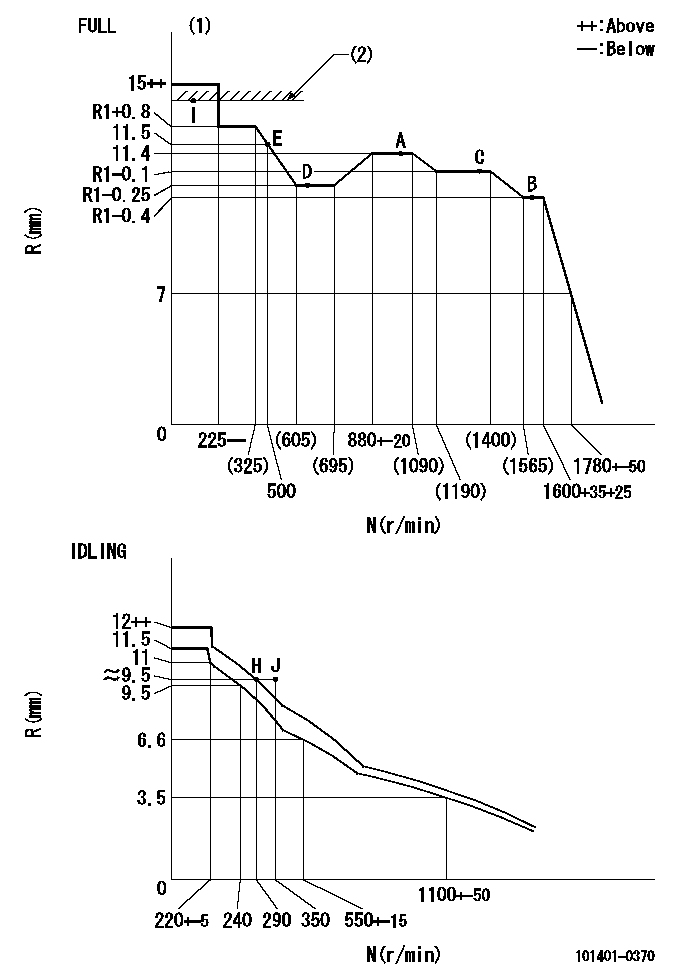
Injection timing adjustment
Direction of rotation (viewed from drive side)
Right R
Right R
Injection order
1-3-4-2
Pre-stroke
mm
3.6
3.55
3.65
Beginning of injection position
Drive side NO.1
Drive side NO.1
Difference between angles 1
Cal 1-3 deg. 90 89.5 90.5
Cal 1-3 deg. 90 89.5 90.5
Difference between angles 2
Cal 1-4 deg. 180 179.5 180.5
Cal 1-4 deg. 180 179.5 180.5
Difference between angles 3
Cyl.1-2 deg. 270 269.5 270.5
Cyl.1-2 deg. 270 269.5 270.5
Injection quantity adjustment
Adjusting point
-
Rack position
11.4
Pump speed
r/min
950
950
950
Average injection quantity
mm3/st.
70.5
69
72
Max. variation between cylinders
%
0
-2.5
2.5
Basic
*
Fixing the rack
*
Standard for adjustment of the maximum variation between cylinders
*
Injection quantity adjustment_02
Adjusting point
H
Rack position
9.5+-0.5
Pump speed
r/min
290
290
290
Average injection quantity
mm3/st.
8
6.7
9.3
Max. variation between cylinders
%
0
-14
14
Fixing the rack
*
Standard for adjustment of the maximum variation between cylinders
*
Injection quantity adjustment_03
Adjusting point
A
Rack position
R1(11.4)
Pump speed
r/min
950
950
950
Average injection quantity
mm3/st.
70.5
69.5
71.5
Basic
*
Fixing the lever
*
Injection quantity adjustment_04
Adjusting point
B
Rack position
11+-0.5
Pump speed
r/min
1600
1600
1600
Average injection quantity
mm3/st.
70.7
67.5
73.9
Fixing the lever
*
Injection quantity adjustment_05
Adjusting point
C
Rack position
11.3+-0.
5
Pump speed
r/min
1300
1300
1300
Average injection quantity
mm3/st.
76
72.8
79.2
Fixing the lever
*
Injection quantity adjustment_06
Adjusting point
D
Rack position
11.15+-0
.5
Pump speed
r/min
650
650
650
Average injection quantity
mm3/st.
53.5
50.3
56.7
Fixing the lever
*
Injection quantity adjustment_07
Adjusting point
E
Rack position
R2(11.5)
Pump speed
r/min
500
500
500
Average injection quantity
mm3/st.
55
51
59
Fixing the lever
*
Injection quantity adjustment_08
Adjusting point
I
Rack position
14.5+-0.
5
Pump speed
r/min
150
150
150
Average injection quantity
mm3/st.
95
95
103
Fixing the rack
*
Timer adjustment
Pump speed
r/min
1350+-50
Advance angle
deg.
0
0
0
Remarks
Start
Start
Timer adjustment_02
Pump speed
r/min
1600
Advance angle
deg.
5
4
5
Remarks
Finish
Finish
Test data Ex:
Governor adjustment
N:Pump speed
R:Rack position (mm)
(1)Torque cam stamping: T1
(2)RACK LIMIT: RAL
----------
T1=47 RAL=(14.5)mm
----------
----------
T1=47 RAL=(14.5)mm
----------
Speed control lever angle

F:Full speed
I:Idle
(1)Stopper bolt set position 'H'
----------
----------
a=5.5deg+-5deg b=41deg+-3deg
----------
----------
a=5.5deg+-5deg b=41deg+-3deg
Timing setting

(1)Pump vertical direction
(2)Position of gear mark 'CC' at No 1 cylinder's beginning of injection
(3)B.T.D.C.: aa
(4)-
----------
aa=13deg
----------
a=(100deg)
----------
aa=13deg
----------
a=(100deg)
Information:
Image1.4.1
5. Remove two 135-8573 Bolts from the 268-0555 Hood Group, and remove the 244-8226 Support Assembly.
Image1.5.1
6. Rework the 244-8226 Support Assembly. Refer to the attached images.
Image1.6.1
7. Remove four 135-8573 Bolts from the 268-0555 Hood Group. Remove the 262-2340 Sheet Assembly.
Image1.7.1
8. Rework the 262-2340 Sheet Assembly. Refer to the attached images.
Image1.8.1
10. Attach the 324-4078 Support Assembly to the 262-2340 Sheet Assembly. Use two 135-8573 Bolts and tighten the bolts to a torque of 60+/-10 Nm.
Image1.9.1
11. To attach the 262-2340 Sheet Assembly to the 268-0555 Hood Group, use the four 135-8573 Bolts from Step-7. Tighten the bolts to a torque of 100+/-20 Nm.
12. To attach the 244-8226 Support Assembly to the 268-0555 Hood Group, use the two 135-8573 Bolts from Step-5. Tighten the bolts to a torque of 100+/-20 Nm.
13. To attach the 196-8236 Filter Assembly to the 244-8226 Support Assembly, use the two 8T-4182 Bolts and two 8T-4121 Washers. Tighten the bolts to a torque of 32+/-3 Nm.
Image1.12.1
14. Remove the present fuel hose which connected between the outlet of the fuel priming pump and the inlet of present filter assembly.
Image1.13.1
15. Install the 099-4437 Gasket to both connectors on the 305-4888 Hose. Connect the 305-4888 Hose to the inlet of the new filter assembly using the 094-9726 Bolt and two 095-2040 Washers. Tighten the bolt to a torque of 34+/-4 Nm. Connect the other end of the 305-4888 Hose to the outlet of the fuel priming pump using the bolt and the washer of the priming pump. Tighten the bolt to a torque of 34+/-4 Nm.
16. Install the 7I-7439 Guard( Length is 700mm) to the 305-4888 Hose.
17. Install the 099-4437 Gasket to both connectors on the 305-4887 Hose. Connect the 305-4887 Hose to the outlet of the new filter assembly and inlet of the present filter assembly. Use the 094-9726 Bolt and two 095-2040 Washers in order to connect the hose to the filter assemblies. Tighten the bolts to a torque of 34+/-4 Nm.
18. Install the 7I-7439 Guard (Length is 760mm) to the 305-4887 Hose.
19. Tighten the 094-9725 Plug with the 095-2040 Washer on top of filter base of current fuel filter and additional fuel filter. Tighten the plug to a torque of 8.8+/-1 Nm.
Image1.18.1
20. Use the 294-1833 Clamp, 7X-2533 Bolt, and the 9X-8256 Washer in order to clamp the fuel hose. Tighten the bolt to a torque of 10+/-1 Nm.
Image1.19.1
21. Use two 294-1831 Clamps, 7X-2535 Bolt, two 9X-8256 Washers, and the 5C-2890 Nut in order to clamp the fuel hose. Tighten the bolt to a torque of 10+/-1 Nm.
22. Re-install the two air intake hoses, using the two 8T-4985 Clamps from Step-4. Tighten the clamps to a torque of 4.5+/-0.5 Nm.
Image1.21.1
23. Re-attach the 244-8212 Cover Assembly to the 268-0555 Hood Group. Use the two 135-8573 Bolts, two 135-8575 Bolts, and two 170-3016 Spacers from Step-2. Tighten the bolts to a torque of 100+/-20 Nm.