Information injection-pump assembly
ZEXEL
101401-0110
1014010110
ISUZU
5156005622
5156005622
Rating:
Service parts 101401-0110 INJECTION-PUMP ASSEMBLY:
1.
_
6.
COUPLING PLATE
7.
COUPLING PLATE
8.
_
9.
_
10.
NOZZLE AND HOLDER ASSY
11.
Nozzle and Holder
12.
Open Pre:MPa(Kqf/cm2)
13.
NOZZLE-HOLDER
14.
NOZZLE
15.
NOZZLE SET
Cross reference number
ZEXEL
101401-0110
1014010110
ISUZU
5156005622
5156005622
Zexel num
Bosch num
Firm num
Name
101401-0110
5156005622 ISUZU
INJECTION-PUMP ASSEMBLY
4BB1 * K
4BB1 * K
Calibration Data:
Adjustment conditions
Test oil
1404 Test oil ISO4113 or {SAEJ967d}
1404 Test oil ISO4113 or {SAEJ967d}
Test oil temperature
degC
40
40
45
Nozzle and nozzle holder
105780-8140
Bosch type code
EF8511/9A
Nozzle
105780-0000
Bosch type code
DN12SD12T
Nozzle holder
105780-2080
Bosch type code
EF8511/9
Opening pressure
MPa
17.2
Opening pressure
kgf/cm2
175
Injection pipe
Outer diameter - inner diameter - length (mm) mm 6-2-600
Outer diameter - inner diameter - length (mm) mm 6-2-600
Tester oil delivery pressure
kPa
157
157
157
Tester oil delivery pressure
kgf/cm2
1.6
1.6
1.6
Direction of rotation (viewed from drive side)
Right R
Right R
Injection timing adjustment
Direction of rotation (viewed from drive side)
Right R
Right R
Injection order
1-3-4-2
Pre-stroke
mm
2.4
2.35
2.45
Beginning of injection position
Drive side NO.1
Drive side NO.1
Difference between angles 1
Cal 1-3 deg. 90 89.5 90.5
Cal 1-3 deg. 90 89.5 90.5
Difference between angles 2
Cal 1-4 deg. 180 179.5 180.5
Cal 1-4 deg. 180 179.5 180.5
Difference between angles 3
Cyl.1-2 deg. 270 269.5 270.5
Cyl.1-2 deg. 270 269.5 270.5
Injection quantity adjustment
Adjusting point
A
Rack position
10.2
Pump speed
r/min
1650
1650
1650
Average injection quantity
mm3/st.
50.3
47.9
52.7
Max. variation between cylinders
%
0
-4
4
Fixing the lever
*
Injection quantity adjustment_02
Adjusting point
B
Rack position
10.2
Pump speed
r/min
1000
1000
1000
Average injection quantity
mm3/st.
50.3
48.8
51.8
Max. variation between cylinders
%
0
-2.5
2.5
Basic
*
Fixing the lever
*
Injection quantity adjustment_03
Adjusting point
C
Rack position
7.8+-0.5
Pump speed
r/min
300
300
300
Average injection quantity
mm3/st.
6.3
5
7.6
Max. variation between cylinders
%
0
-14
14
Fixing the rack
*
Injection quantity adjustment_04
Adjusting point
D
Rack position
10.8+-0.
5
Pump speed
r/min
500
500
500
Average injection quantity
mm3/st.
38.3
Fixing the lever
*
Remarks
After startup boost setting
After startup boost setting
Injection quantity adjustment_05
Adjusting point
E
Rack position
14.5+-0.
5
Pump speed
r/min
100
100
100
Average injection quantity
mm3/st.
47
47
Fixing the lever
*
Remarks
After startup boost setting
After startup boost setting
Timer adjustment
Pump speed
r/min
1000+-50
Advance angle
deg.
0
0
0
Remarks
Start
Start
Timer adjustment_02
Pump speed
r/min
1200
Advance angle
deg.
0.9
0.4
1.4
Timer adjustment_03
Pump speed
r/min
1450
Advance angle
deg.
2.1
1.6
2.6
Timer adjustment_04
Pump speed
r/min
1650
Advance angle
deg.
3
2.5
3.5
Timer adjustment_05
Pump speed
r/min
-
Advance angle
deg.
5
5
5
Remarks
Measure the actual speed, stop
Measure the actual speed, stop
Test data Ex:
Governor adjustment
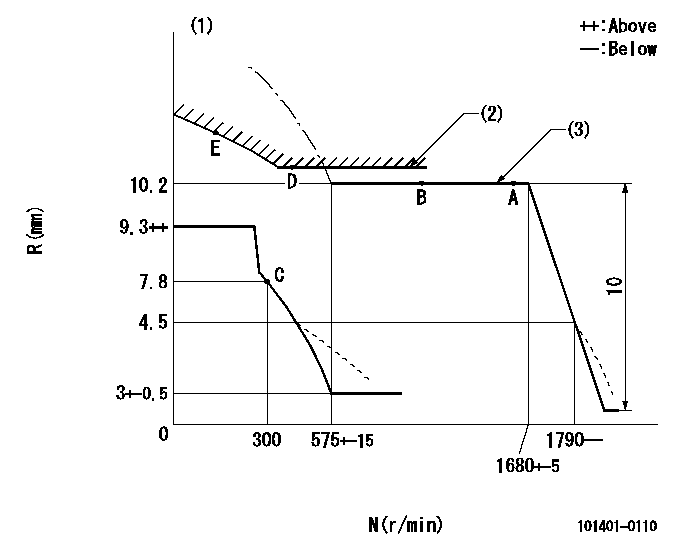
N:Pump speed
R:Rack position (mm)
(1)Beginning of damper spring operation: DL
(2)Set using excess fuel device for starting: SXL
(3)Deliver without the torque control spring operating.
----------
DL=4.5-0.2mm SXL=10.2+0.2mm
----------
----------
DL=4.5-0.2mm SXL=10.2+0.2mm
----------
0000000901
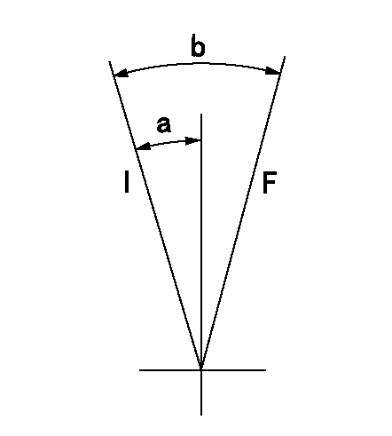
F:Full load
I:Idle
----------
----------
a=16deg+-5deg b=27deg+-3deg
----------
----------
a=16deg+-5deg b=27deg+-3deg
Information:
Maintenance
Every 20,000 miles (30,000 km) or 1,000 hours, clean the oil drain pipe from turbocharger to sump, also turbocharger compressor wheel and cover.
T1Remove the air inlet duct and compressor housing and check for dirt or dust build-up (see Fig. T.1).Remove all foreign matter - determine and correct cause of build up.Use soft brush on compressor wheel as uneven deposits can affect rotor balance and cause bearing failure.With the compressor housing removed, push the compressor wheel towards the turbine wheel and turn rotating assembly by hand: check for binding and rubbing. Listen carefully for unusual noises. If binding or rubbing is evident, remove the turbocharger for dismantling and inspection.To Remove Turbocharger
Disconnect turbocharger inlet and outlet connections.Disconnect exhaust pipe.Remove oil supply pipe and release oil drain pipe.Release turbocharger outlet assembly from the cylinder block.
T2Remove turbocharger from exhaust manifold, (see Fig. T.2).Seal open engine connections.Airesearch T-31 (see Fig. T.3)
T3Dismantling
Clean the exterior with a pressure spray of a non-caustic cleaning solvent before dismantling. Dismantle only as required to make necessary inspection or repairs. Note: The 'Wastegate' unit where fitted, cannot be dismantled. See page T.4 for service/calibration instructions. As each part is removed, place in a clean container to prevent loss or damage.Remove the bolts, clamps and lockplates which hold the compressor and turbine housings to the centre housing group. Tap the housings with a soft faced hammer if force is needed for removal. Exercise caution when removing housings to prevent damage to compressor or turbine wheel. Once damaged, they cannot be repaired. Never attempt to straighten bent compressor or turbine blades-replace the faulty component.Place the centre housing group in a suitable holding fixture which will prevent the turbine wheel from turning.Use a T-handled wrench when removing the compressor wheel locknut to avoid possible bending of the shaft.Lift the compressor wheel off the shaft. Remove the shaft wheel from the centre housing keeping shaft central with bearings until clear of centre housing. The turbine wheel shroud is not retained to the centre housing and will fall free when the shaft wheel is removed.Remove lockplates and bolts from back plate.Tap backplate with soft mallet to remove from recess in centre housing.Remove thrust collar and thrust bearing from centre housing.Remove bearings and retainers from centre housing. Discard rubber sealing ring.Cleaning
Before cleaning, inspect all parts for signs of rubbing, burning or other damage which might not be evident after cleaning.Soak all parts in clean non-caustic carbon solvent. After soaking, use a stiff bristle brush and remove all dirt particles. Dry parts thoroughly. Normally a light accumulation of carbon deposits will not affect turbine operation.Internal Parts Inspection (see Fig. T.4)
T4Parts must now show signs of damage, corrosion or deterioration. Threads must not be nicked, crossed or stripped.The turbine wheel must show no signs of rubbing and vanes must not be torn or worn to a feather edge. The shaft must show little signs of scoring, scratches or seizure with the bearings.The compressor must show no signs of rubbing or damage from foreign matter. The compressor wheel
Have questions with 101401-0110?
Group cross 101401-0110 ZEXEL
Isuzu
101401-0110
5156005622
INJECTION-PUMP ASSEMBLY
4BB1
4BB1