Information injection-pump assembly
ZEXEL
101400-9040
1014009040
YANMAR
12995351020
12995351020

Rating:
Cross reference number
ZEXEL
101400-9040
1014009040
YANMAR
12995351020
12995351020
Zexel num
Bosch num
Firm num
Name
Calibration Data:
Adjustment conditions
Test oil
1404 Test oil ISO4113 or {SAEJ967d}
1404 Test oil ISO4113 or {SAEJ967d}
Test oil temperature
degC
40
40
45
Nozzle and nozzle holder
105780-8140
Bosch type code
EF8511/9A
Nozzle
105780-0000
Bosch type code
DN12SD12T
Nozzle holder
105780-2080
Bosch type code
EF8511/9
Opening pressure
MPa
17.2
Opening pressure
kgf/cm2
175
Injection pipe
Outer diameter - inner diameter - length (mm) mm 6-2-600
Outer diameter - inner diameter - length (mm) mm 6-2-600
Overflow valve
131424-1520
Overflow valve opening pressure
kPa
157
157
157
Overflow valve opening pressure
kgf/cm2
1.6
1.6
1.6
Tester oil delivery pressure
kPa
157
157
157
Tester oil delivery pressure
kgf/cm2
1.6
1.6
1.6
Direction of rotation (viewed from drive side)
Right R
Right R
Injection timing adjustment
Direction of rotation (viewed from drive side)
Right R
Right R
Injection order
1-3-4-2
Pre-stroke
mm
3.6
3.55
3.65
Beginning of injection position
Drive side NO.1
Drive side NO.1
Difference between angles 1
Cal 1-3 deg. 90 89.5 90.5
Cal 1-3 deg. 90 89.5 90.5
Difference between angles 2
Cal 1-4 deg. 180 179.5 180.5
Cal 1-4 deg. 180 179.5 180.5
Difference between angles 3
Cyl.1-2 deg. 270 269.5 270.5
Cyl.1-2 deg. 270 269.5 270.5
Injection quantity adjustment
Adjusting point
A
Rack position
9.8
Pump speed
r/min
950
950
950
Average injection quantity
mm3/st.
64.5
63.5
65.5
Max. variation between cylinders
%
0
-2.5
2.5
Basic
*
Fixing the lever
*
Injection quantity adjustment_02
Adjusting point
C
Rack position
6.7+-0.5
Pump speed
r/min
590
590
590
Average injection quantity
mm3/st.
10.5
9.5
11.5
Max. variation between cylinders
%
0
-15
15
Fixing the rack
*
Injection quantity adjustment_03
Adjusting point
D
Rack position
10.4++
Pump speed
r/min
100
100
100
Average injection quantity
mm3/st.
70
65
75
Fixing the lever
*
Rack limit
*
Test data Ex:
Governor adjustment
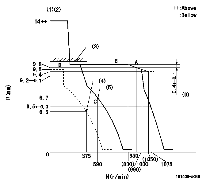
N:Pump speed
R:Rack position (mm)
(1)Target notch: K
(2)Tolerance for racks not indicated: +-0.05mm.
(3)RACK LIMIT
(4)Set idle sub-spring
(5)Main spring setting
(6)Rack difference from N = N1
----------
K=14 N1=750r/min
----------
----------
K=14 N1=750r/min
----------
Speed control lever angle

F:Full speed
I:Idle
(1)Stopper bolt setting
----------
----------
a=(6deg)+-5deg b=(16deg)+-5deg
----------
----------
a=(6deg)+-5deg b=(16deg)+-5deg
Stop lever angle
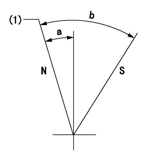
N:Pump normal
S:Stop the pump.
(1)Normal
----------
----------
a=7deg+-5deg b=53deg+-5deg
----------
----------
a=7deg+-5deg b=53deg+-5deg
Timing setting

(1)Pump vertical direction
(2)Position of camshaft's key groove at No 1 cylinder's beginning of injection
(3)-
(4)-
----------
----------
a=(60deg)
----------
----------
a=(60deg)
Information:
9-1345. Assemble screw to secure end plate of crankcase breather to the oil sump.Fig. 9-1346. Turn the engine over so that the cylinders are in the upward vertical position.
9-1357. Secure front vertical plate to cylinder. Secure fuel pipe for flame-type heater plug by clip.Fig. 9-135
9-1368. Position air cowling base, screw in central bolt and fit two washers. (Example: F5L)Fig. 9-136
9-1379. Install the oil cooler fitted with a a new rubber O-ring to seal against the lower part of the air cowling. Tighten the pipe unions.Fig. 9-137
9-13810. Fit bolts with washers for oil cooler.Fig. 9-138
9-13911. Secure exhaust air baffle.Fig. 9-139
9-14012. Fit rear vertical plate.Fig. 9-140
9-14113. Fit cooling blower to front-end cover.Fig. 9-141
9-14214. Position the upper cover plate on the cylinder heads.Fig. 9-14215. Connect fuel delivery lines, fitting new rubber mounting strip and new rubber sleeves.
9-14316. Connect the leak-off lines between the injectors and from one of the injectors to the injection pump. Assemble the long hollow screw in cylinder 1 and plug it to prevent the ingress of dirt.Fig. 9-143
9-14417. If the engine has a flame-type heater system, mount the solenoid valve on the front vertical plate.Fig. 9-14418. Install bracket mounting new fuel and lubricating oil filters and connect the fuel lines, fitting new gaskets.
9-14518.1. See Fig. 9-145 for F3L.
9-14618.2. See Fig. 9-146 for F4/6L.
9-14719. Install temperature sensors/contactors in cylinder heads. Starting Fig. 9-147 the following notes are applicable.
9-148 Sensor and contactor differ by their length. Fig. 9-148 shows sensor at left and contactor at right. Important:The direct-injection (D) and two-stage combustion (W) engines have contact makers (switches) of different temperature limits:D = 150° CW = 170° C
9-149 Cylinder numbering.Fig. 9-149The temperature sensor is secured to pickup point 1. A second sensor or a contactor is secured to point 2.
9-15020. Hook in the air cowling at the top and close at the bottom.Fig. 9-150
9-15121. Fit a new gasket in the oil filler cap. Replace the rubber gasket by a cork gasket.Fig. 9-15122. Close the oil filler; insert oil dipstick.
9-15223. Where an extra-long oil filler neck and dipstick guide have been provided, install filler neck with new O-ring in front-end cover and secure to cooling blower. Install dipstick guide.Fig. 9-152
9-15324. If the engine is fitted with an air compressor the oil return hole in the front cover plate must be left open. If the engine is not fitted with an air compressor a plug coated with jointing compound should be screwed into the oil return hole.Fig. 9-153 The next three operations apply only if the engine is fitted with an air compressor.
9-15425. Coat a new rubber O-seal with grease and stick it in position on the bracket of the air compressor.Fig. 9-154
9-15526. Mount the air compressor with bracket on the front cover plate.Fig. 9-155
9-15627. Install the high-pressure oil line, fitted with new gaskets, running from the oil gallery to the air compressor and tighten the female screws.Fig. 9-156
9-15728. Install new gaskets for the induction and exhaust manifolds with the flat end upwards.Fig. 9-157 On engines of more recent design, fit